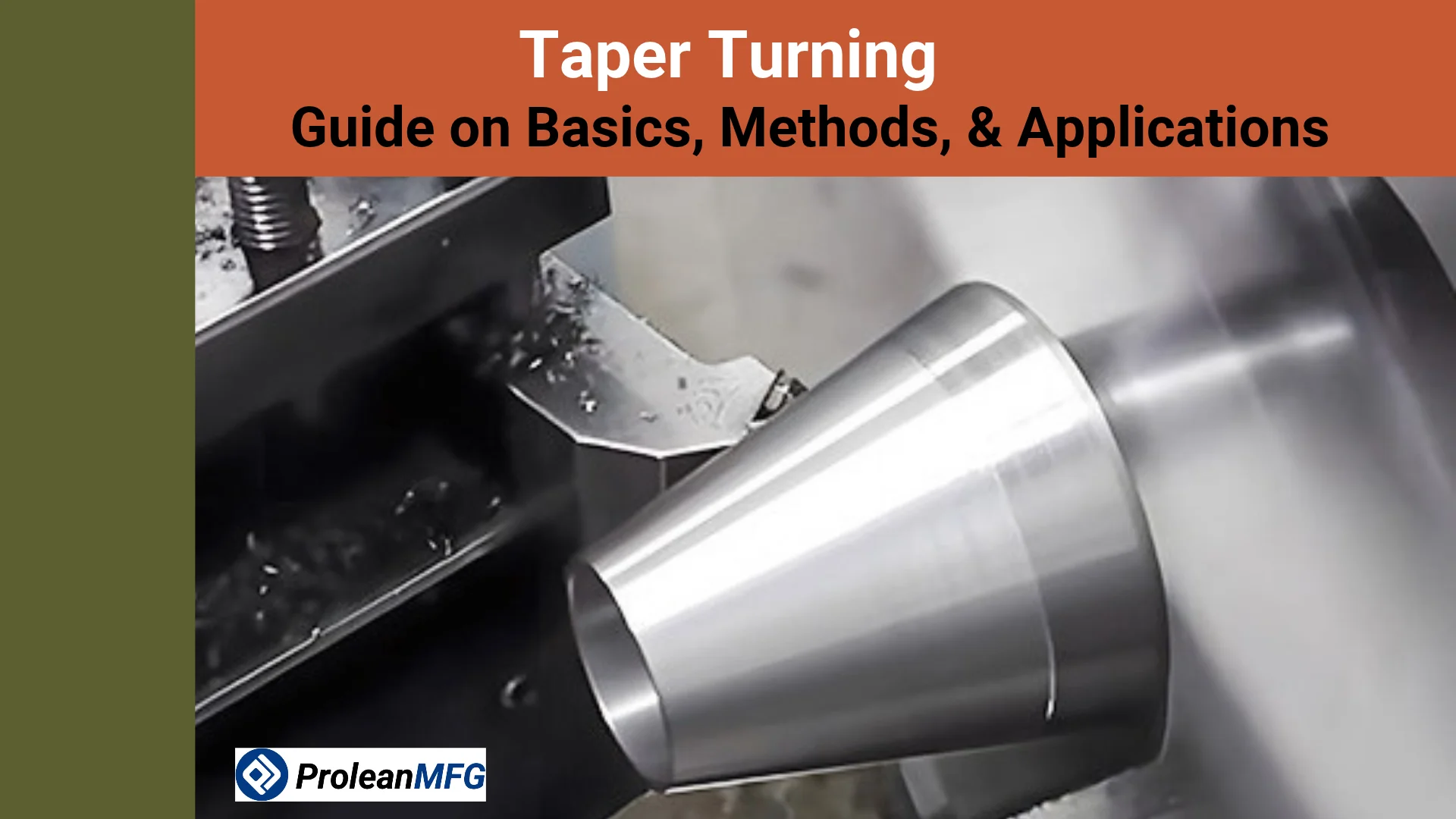
Taper turning is useful where sealing, location, or torque transmission is required between two components without fasteners. The Morse taper shank on a twist drill, the tapered crankshaft on a flywheel hub, and the tapered pipe threads in drilling equipment all use an accurately produced cone. CNC turning is a reliable production method for repeat work.
On paper, the geometry of a taper is simple. However, cutting a taper requires special machining methods and expertise. A minimal off-center height or half-angle error can cause mating part contact errors.
Taper turning quality depends on setup, geometry, and the inspection methods. Check the sections below for a walkthrough of taper production, calculation, and verification for assembly.
Key Takeaways
- Taper turning moves the cutting tool at an angle to the spindle axis. It produces a cone, which can have a female (internal) taper or male (external) taper
- Five core taper turning methods: Compound slide, tailstock offset, taper attachment, form tool, and CNC programming.
- Verification of mating tapers should include more than just diameter measurement; Gauge and contact pattern checks are crucial.
What is Taper Turning?
Taper turning is a lathe machine operation that feeds the cutting tool at an angle to produce a gradual diameter change along the workpiece length. The part produced by taper turning can be an internal cone (female taper) or an external cone (male taper). The gradual change in diameter distinguishes a taper from the discrete steps made by step turning.
A schematic of taper turning is shown below.
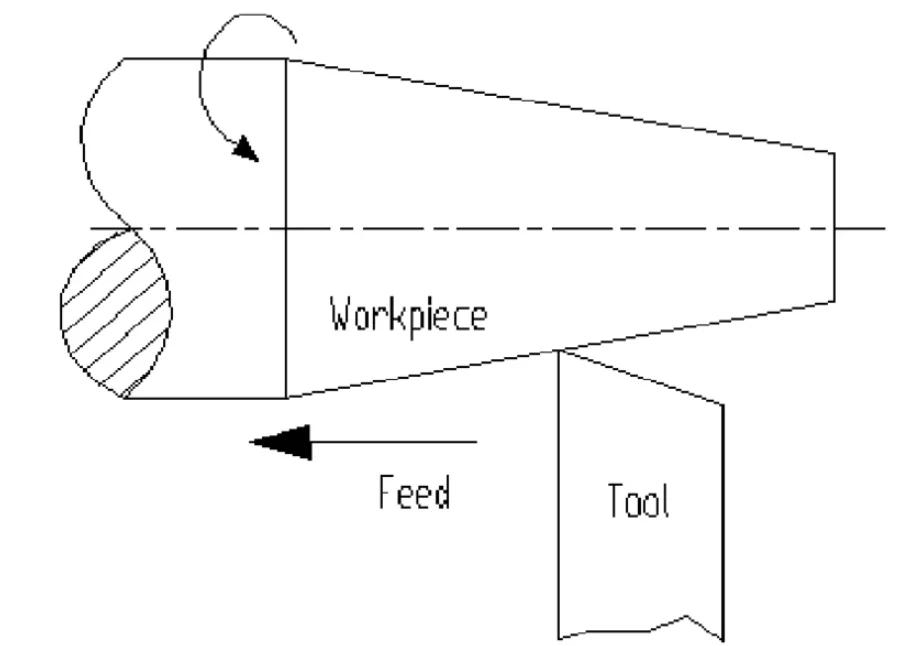
Taper turning schematic
Importance of Tapered Features in Machined Components
Tapered features can be used for alignment, torque transmission, and sealing applications.
Alignment: Concentricity is achieved when the male member self-centers in the female member. A cylindrical clearance fit cannot produce such concentricity.
Torque Transmission: Tapers can be designed to self-hold and transmit torque by friction. Morse tapers apply this principle.
Sealing: The metal-to-metal sealing on the conical seat line is used in fittings and valves.
Types of Taper: Self-Holding vs Self-Releasing
There are two main types of taper: Self-holding and self-releasing.
Self-holding: This taper locks the two parts through friction because of the shallow angle. Examples include Morse, Brown & Sharpe, and Jarno tapers. Morse tapers are approximately 1:20. The exact ratio varies by size. [2]
Self-releasing: These types of taper feature a steeper angle. The two parts must be clamped. It is easier to release this taper. Milling machines contain an excellent example of a self-releasing taper – the 7:24 steep taper
These types of taper are summarized in the table below.
| Taper | Approximate ratio | Types of taper | Typical application |
| Morse | 1:20 | Self-holding | Reamers, drill shanks |
| Brown & Sharpe | 1:24 | Self-holding | Milling arbors |
| Jarno | 1:20 | Self-holding | Tooling fits, machine tool spindles |
| 7:24 steep | 7:24 (about 1:3.4) | Self-releasing | CNC tool holders, milling machine spindles |
How Taper Turning Works
Most lathe setups follow a sequence of understanding the drawing, calculating taper parameters, selecting the taper turning method, selecting the tooling & cutting data, clamping the workpiece, cutting a taper, and inspecting the final piece.
Drawing Details – Confirm the taper specification in terms of diameter, length, included angle, half-angle, and ratio (1:x). Confirm tolerances.
Taper Parameters – Use Geometry of a Taper for the ratio and half-angle, and Important Taper Turning Calculations for tailstock offset.
Taper Turning Method – Factors to consider when choosing a taper turning method include form, length, angle, and production volume.
- CNC – Tight tolerances and complex profiles
- Compound slide – Short tapers
- Taper attachment – Manual process
- Tailstock offset – Long, gentle external tapers
Tooling & Cutting Data
- Choose material geometry and insert grade.
- Leave enough clearance for internal cuts.
- Use N = (1000 × Vc) / (π × D) for the spindle speed
Clamping the Workpiece – Minimum overhang should be used when holding the part. Slender parts should be held using a tailstock. A dial indicator helps check the runout.
Cutting a Taper – Set the cutting edge on the workpiece centerline. Rough with a deeper cut, then take a light finishing pass. On a CNC lathe in constant surface speed mode, spindle rpm changes as the cutting diameter changes.
Inspection – Check taper angle with a sine bar and dial indicator, or use a taper gauge to verify fit. Use marking blue to confirm the contact pattern on mating surfaces. Compare the measured dimensions and angle with the drawing tolerances. For general limits, see our guide to CNC machining tolerances.
Geometry of a Taper
There are three core dimensions of a taper: Taper length, small diameter, and large diameter. Other values are taper ratio and taper angle.
A taper ratio is written as 1:x, where x = L / (D − d). Use the same units for both diameters and the axial length.
Taper ratio = (D − d) / L
Half-angle = arctan[(D − d) / (2 × L)]
Included angle = 2 × half-angle
D is the large diameter, d is the small diameter, and L is the axial length of the taper.
Here is a worked example:
D = 30 mm, d = 20 mm, L = 50 mm.
Ratio = 50 / 10, so the taper is 1:5.
Half angle = arctan(10 / 100) = 5.71°.
Included angle = 2 × 5.71° = 11.42°.
Machining Challenges in CNC Taper Turning
The core machining challenges in CNC taper turning are incorrect taper angle, surface irregularities, dimensional inconsistency of the taper, tool wear, and poor concentricity. These issues are mostly tied to setup, a machining requirement taper turning is more sensitive to than straight turning.
- Incorrect Taper Angle: This happens when the machinist miscalculates the tailstock offset or compound scale. Incorrect coordinate programming can also cause a taper angle error.
- Surface Irregularities: Like in other types of machining, surface irregularities when cutting a taper can occur due to a dull cutting tool edge or excessive overhang. Resonance is also a possible cause of this problem.
- Dimensional Inconsistency: The taper can be dimensionally inconsistent due to inconsistent clamping force, insert wear drift, and thermal expansion of the workpiece and spindle.
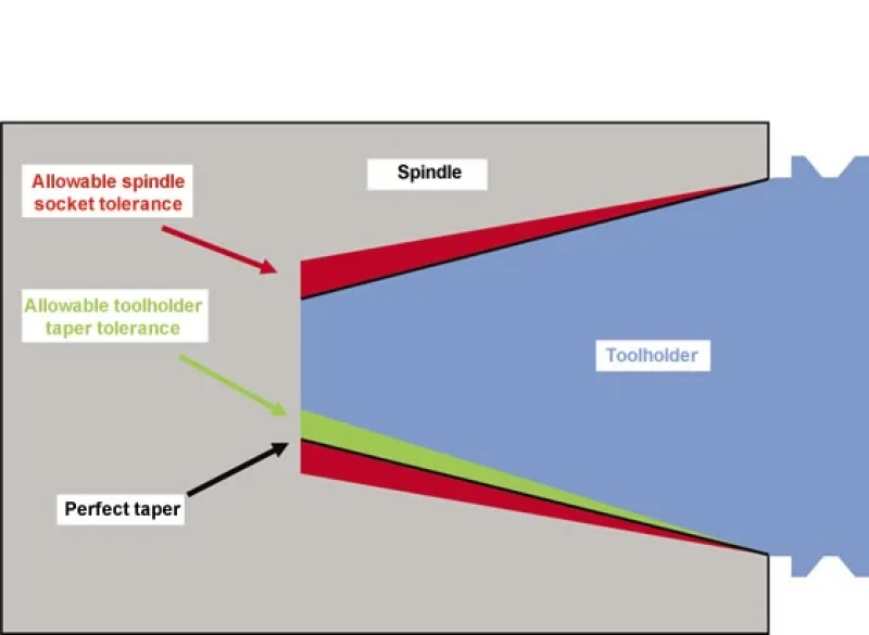
Tapered spindle
- Tool Wear: As the cutting tool wears out, the gap between the programmed path and the cutting edge grows. Every subsequent batch has a different taper angle and a larger diameter.
- Poor Concentricity: Concentricity errors in taper turning are caused by center runout, uneven chuck pressure, and misalignments. Like the other issues, it should be avoided to ensure quality sealing and fit.
CNC Taper Turning Materials
The range of taper turning materials is wide, comprising plastics, composites, aluminum, brass, copper, alloy steels, carbon steels, titanium, and stainless steels.
Plastics: Plastics suitable for taper turning include PEEK, acetal, and nylon. Low clamping force and sharp positive-rake geometry ensure thermal safety and distortion-free machining.
Composites: Composites are abrasive, so they can promote fast tool wear. They also delaminate easily. Diamond-coated and PCD tooling are recommended for cutting a taper for composites.
Aluminum Alloys: Options for cutting a taper include alloy 2024, alloy 7075, alloy 6061, and alloy 6082. Each of these has its strengths. For instance, 2024 is recommended for fatigue performance, while 7075 offers an excellent strength-to-weight ratio.
Brass: Brass is an ideal material for taper turning due to its excellent surface finish and machinability.
Copper: Copper taper turning requires consideration for the material’s ductility and gumminess. A generous coolant should accompany a sharp cutting tool with a positive rake.
Alloy Steels: Alloy steels are hard and strong, properties that affect the taper turning strategy. Coated carbide tooling is recommended for these steels. The machining speed can go up to 200 m/min.
Carbon Steels: AISI 1018, A36, and other carbon steels are popular in taper turning for axles and shafts. Plain carbon steels (0.2 to 0.25% C) offer excellent machinability. Machinability is typically lower for percentages lower or higher than this.
Titanium: The material’s high strength and low thermal conductivity make standard taper-turning strategies ineffective. Machinists use rigid setups and high-pressure coolants.
Stainless Steels: With a tendency to work-harden during machining, stainless steels require a positive feed. Keep the tool feeding to avoid dwelling. See our stainless steel turning guide for tooling and feed considerations.
Main Taper Turning Methods
Taper turning can be executed using any of these methods: Compound slide, tailstock offset, taper attachment, form tool, or CNC programming.
- Compound Slide: Set the compound feed direction to the taper half-angle relative to the spindle axis, using the lathe’s scale reference. Clamp the swivel base and feed by hand. Limited slide travel makes this method suitable for short, steep tapers.
- Tailstock Offset: Two centers hold the part. The tailstock is shifted slightly so the toolpath can be at a slight angle to the workpiece axis. A taper forms as the tool travels and cuts the tilted part. This method suits long, shallow external tapers turned between centers.
- Taper Attachment: An angled guide bar moves the cross slide as the carriage travels, while the centers stay aligned. The attachment suits long, accurate internal or external tapers within its available travel.
- Form Tool: A taper-shaped tool is plunged into the rotating workpiece. The plunge cut is designed for chamfers and very short tapers.
- CNC Programmed: The control interpolates the taper path for repeat production. Feasible lengths, angles, and profiles depend on machine travel and tool clearance.
| Taper turning method | Taper length | Internal/external | Accuracy | Best volume |
| Compound slide | Short | Both | Moderate, depends on operator | Low volume |
| Tailstock offset | Long | External | Moderate | Low-medium |
| Taper attachment | Long | Both | High | Low-medium |
| Form tool | Very short | External chamfers | Tool-dependent | Medium-high |
| CNC programming | Within machine travel | Both | High | Medium-high, repeat work |
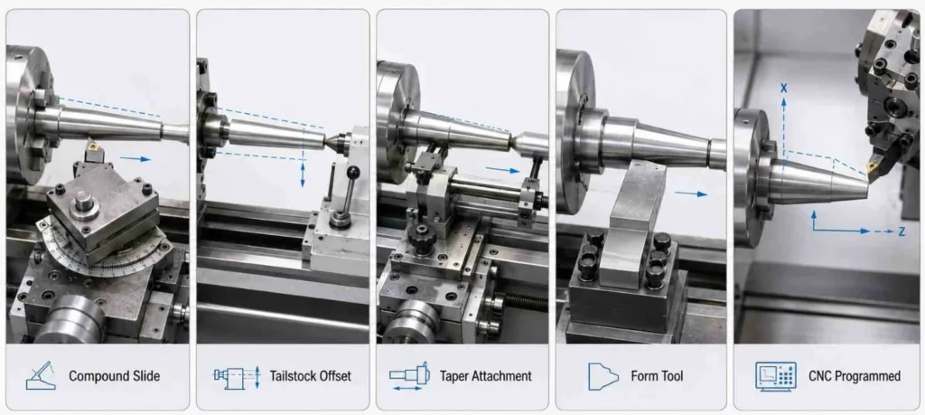
Taper turning methods
Tooling Selection for Taper Turning
A single-point tool is preferred for most taper turning jobs because it is easier to control. Choose the tool geometry, clearance, and insert grade for the workpiece material and setup.
- Tool Geometry & Clearance – Sufficient end clearance and a small nose radius are required to prevent the heel from rubbing the cone.
- Type of Material – Coated carbide is a common choice for steels. Sharp uncoated carbide or polycrystalline diamond (PCD) inserts can suit aluminum and copper alloys, depending on the alloy and finish requirements.
- Tool Properties (rigid, sharp, setup requirements) – The cutting edge should be set at the center height. A rigid tool holder with minimum overhang is also recommended.
- Cutting Data – For coated carbide on carbon steel, 100–200 m/min is an example starting range. Choose the speed and finishing feed from the insert maker’s data for the specific grade and setup.
Compute N = (1000 × Vc) / (π × D) for spindle speed in rpm,
where N is spindle speed (rpm),
Vc is cutting speed (m/min), and
D is the workpiece diameter (mm).
For a manual lathe running at fixed rpm, calculate the spindle speed using the largest cutting diameter. In CNC constant surface speed mode, the control adjusts rpm as the tool moves along the taper.
Industrial Applications of Taper Turning
| Industry | Common Taper Part |
| Aerospace | Tooling tapers, hydraulic fittings |
| Automotive | Steering knuckle seats, axle and hub tapers |
| Medical devices | Orthopaedic stem taper joints |
| Pneumatics & hydraulics | Valve cone seats |
| Energy sector | Tapered pipe connections |
| Machine tool manufacturing | Morse and 7:24 spindle tapers |
Are you in these industries and require taper-turned parts? See our CNC turning services.
Important Taper Turning Calculations
Most manual tapers are set on two calculations: The tailstock offset and the compound rest angle. Both use the taper length, large diameter, and small diameter. Therefore, they should be computed before the initial cut.
- Tailstock offset
For a shallow external taper turned between centers, calculate the tailstock offset (S) as follows:
S = (D – d) L_total / (2 L_taper)
Where:
D = Large diameter of the taper
d = Small diameter of the taper
L_total = Effective distance between the centers, accounting for how far they enter the workpiece
L_taper = Length of the tapered portion
- Compound Rest Angle for Accurate Tapers
The taper angle (α) can be calculated from the large and small diameters (D and d) and the length of the taper (L_taper) using the formula:
tan(α / 2) = (D – d) / (2 * L_taper)
The included angle is α = 2 arctan((D – d) / (2 L_taper)). Set the compound feed direction at α / 2 relative to the spindle axis and use the machine’s scale reference to determine the dial reading.
For standard taper calculations and tailstock setover, see The Machinist, §18 and Table XIV. [1]
Advantages and Limitations of Taper Turning
Here is a summary of the advantages and limitations of taper turning methods.
Advantages of taper turning methods:
- No added fasteners in joints
- Quick assembly
- Dependable metal-to-metal sealing
Limitations of taper turning methods:
- Restricted length – compound slide
- Dedicated measurement equipment is required for tight tolerances
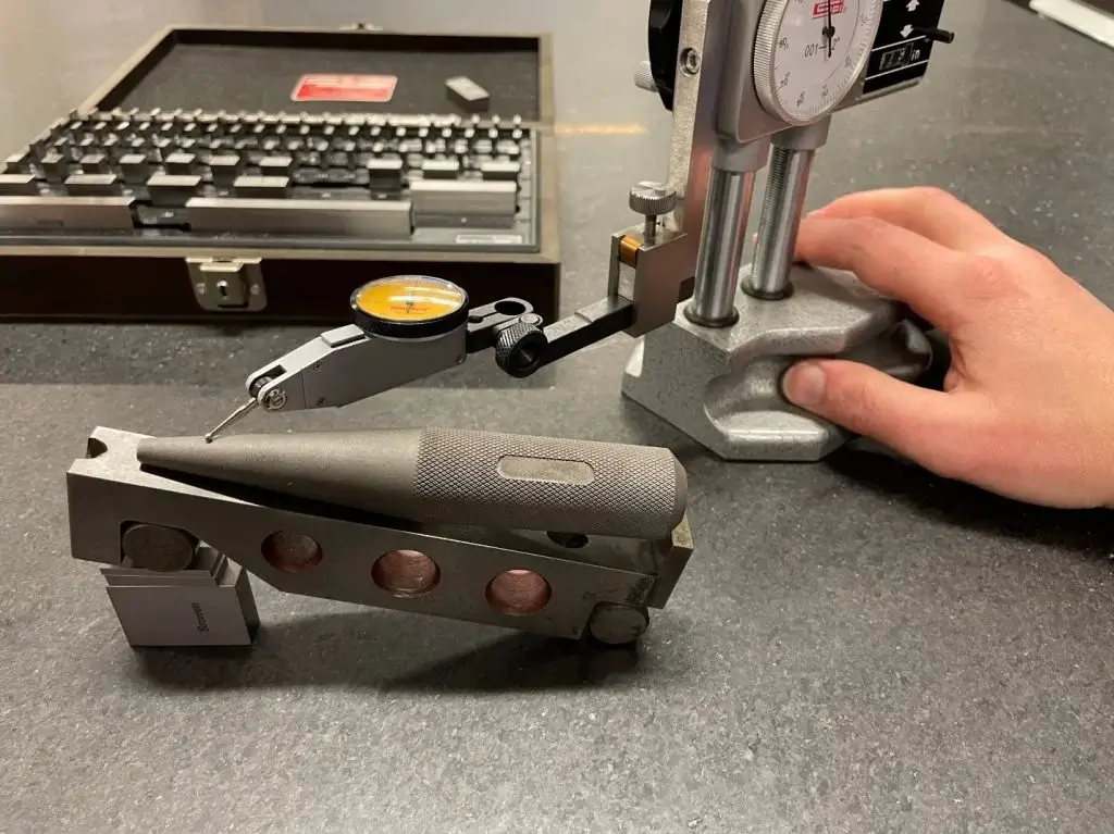
Taper measurement
Taper Turning Best Practices
Here are some of the best practices we use when cutting a taper.
- Clamp the workpiece firmly with minimal overhang. Verify the cutting edge against a known center-height reference before the first cut.
- When feeding with the compound slide, secure the swivel base after setting the angle. Adjust the gibs to remove play while allowing smooth slide travel.
- Make a trial cut on scrap and verify the taper with a gauge before cutting the production part.
- If tool or workpiece deflection leaves stock after finishing, repeat the pass at the same tool setting and recheck the taper.
In Conclusion
Taper turning provides sealing, alignment, and torque transmission in a wide range of applications. Accuracy of the machining process depends on the geometry, taper turning method, and calculations.
Repeat taper production to tight tolerances is best done on a CNC machine. This route offers dependable in-process checks and final verification of machined parts. When sourcing a provider for taper turning parts, focus on machining capability, inspection methods, and process documentation.
ProleanMFG checks turned parts against the drawing and can provide dimensional inspection reports on request. We confirm achievable taper tolerances during engineering review based on the part geometry, material, and inspection method. See our quality and inspection process for available reports.
Contact us today with your taper turning CAD drawing. An engineer will respond with a quote within 24 hours.
FAQs
What is taper turning?
Taper turning is an operation performed on the lathe. The cutting tool is angled to the workpiece axis. The result is a cone with a varying diameter. The cone can be internal (female) or external (male).
How do you calculate a taper?
Divide the difference between the large and small diameters (D − d) by the axial taper length L to get the taper ratio. For the half-angle, use arctan[(D − d) / (2 × L)].
What does a 1:20 taper mean?
A 1:20 taper changes 1 mm in diameter over 20 mm of axial length. The included angle is about 2.86°, and the half-angle is about 1.43°. Jarno tapers use 1:20. Morse taper ratios vary by size.
Which taper turning method is best for long tapers?
A taper attachment suits accurate internal and external tapers on a manual lathe. Tailstock offset suits shallow external tapers turned between centers, and CNC turning is a good choice for repeat production.
References
[1] U.S. War Department, The Machinist (TM 10-445), §18 and Table XIV.
[2] ISO 296:1991, Machine tools — Self-holding tapers for tool shanks. See the Morse taper dimensions in the table preview.