
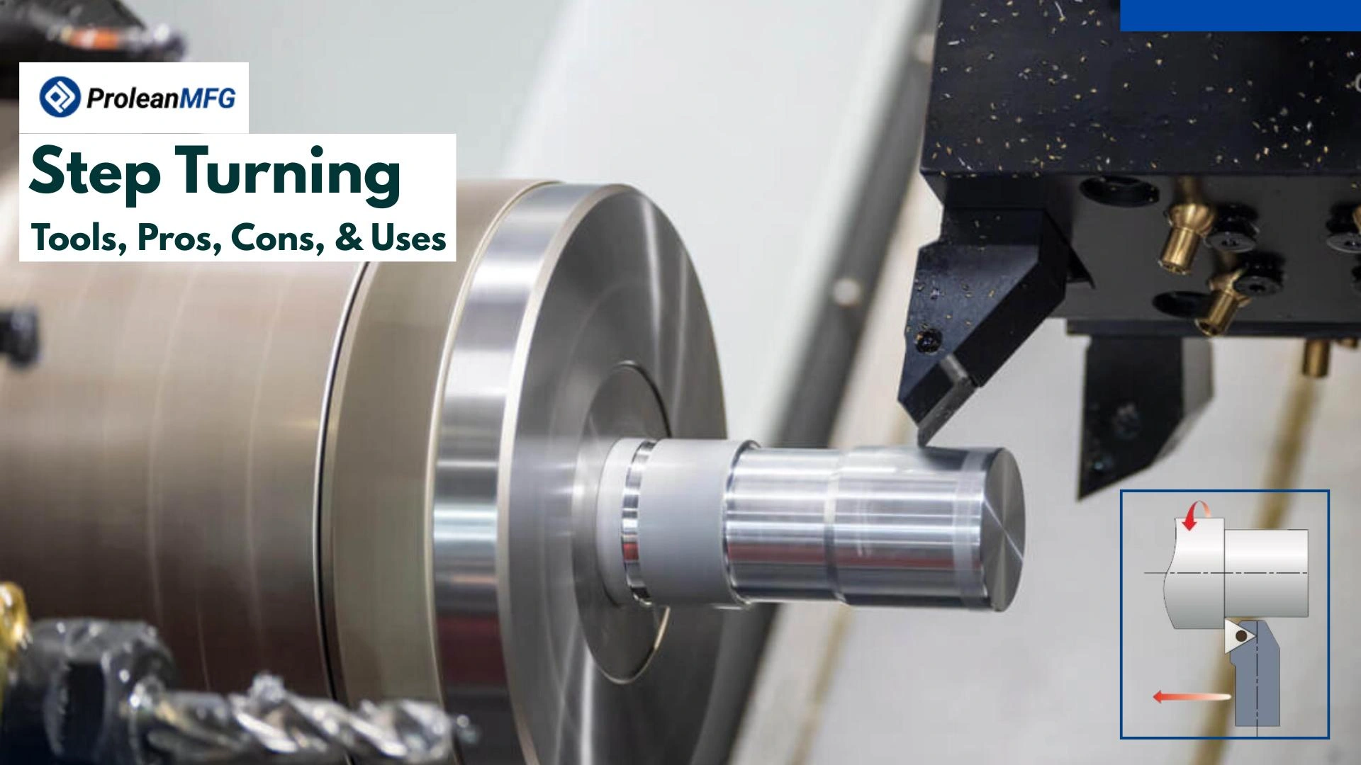

Have you seen a transmission shaft with multiple bearing seats? Well, those sections with different diameters are shaped using a step-turning process.
Like this, machining of other diverse mechanical parts involves the step turning process to achieve the controlled diameter transitions across different sections of a cylindrical shaft.
Although the standard CNC turning process can produce such perpendicular sections with distinct diameters, step turning reduces setup & machining time, improves production consistency, and optimizes the overall cost.
This article will elaborate on the CNC step-turning process, the required tools, challenges, pros and cons, and application examples.
Let’s get started!
What is Step Turning?
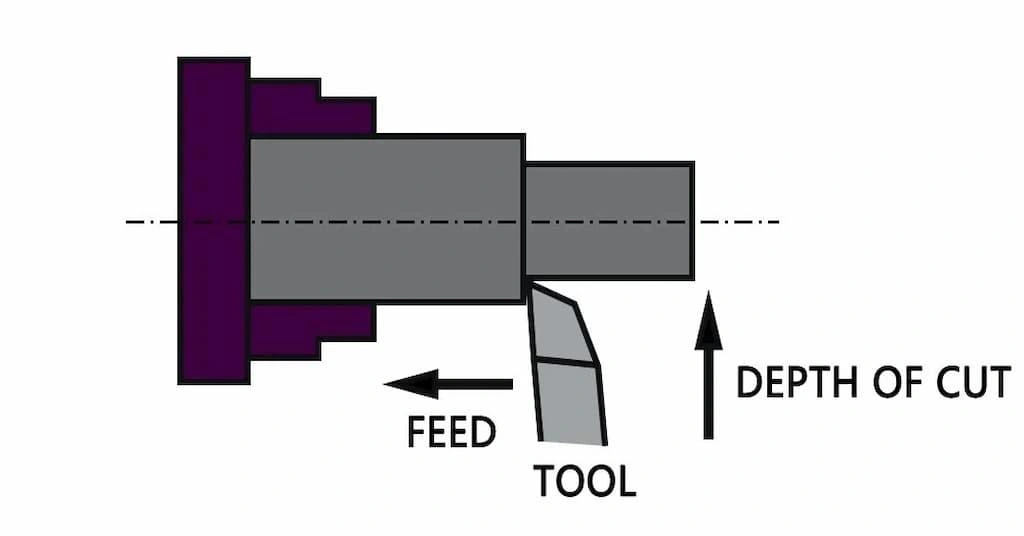
step turning diagram
Step turning is a specialized CNC turning process that involves controlled material removal from a rotating workpiece to create multiple sections (called “steps”) with different diameters along its length. The transition between these sections is maintained at 90°. Meanwhile, each section has a uniform diameter, although it differs from the others.
You can perform a step turning operation on a CNC lathe or turning centers. A straight cutter or a parting tool is fed parallel to the workpiece’s rotation axis to form two or more distinct diameter sections.
What is the Main Purpose of the Step Turning Process?
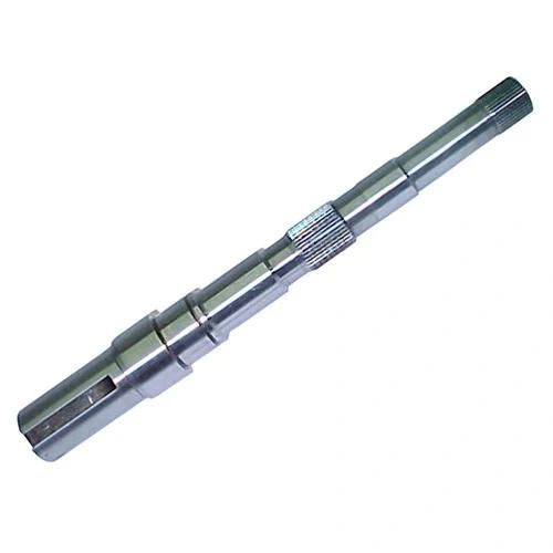
step-turned shaft
The main purpose of the step turning process is to produce shafts having two or more sections with different diameters, each other stepped at 90 degrees. These kinds of shafts are crucial in assembly fitting, mounting of secondary components, and better load distribution.
Working of the CNC Step Turning Process
The working principle of step turning is “controlled material removal at desired axial sections with sudden changes in diameters ( 90°)”: It is achieved through adjusting the depth of cuts and multiple tool passes. The process involves multiple steps, including design & programming, machine setup, turning stage, and post-processing.
Next, let’s look at the main steps involved in the CNC step turning process.
Design & Programming
As with every other CNC turning operation, the first step is to create a manufacturable design for the part to be step-turned in computer software. Then, generate a CNC program file for that design.
Machine Setup
Mount a single-point cutter or parting tool on the tool post, and clamp the workpiece in the lathe’s chuck. Consequently, ensure precise alignment between the cutter or parting tool and the workpiece.
Turning Process
As the CNC program runs, the material is removed across the length to achieve a uniform diameter. Then, the tool removes material from specific sections, varying the depth of cut.
Furthermore, while setting the cutting depth, it is recommended to use up to 2 mm for roughing & 0.5 mm for finishing passes.
Post-Processing
Once turning is complete and the piece is part-off, process it with deburring, beadblasting, sanding, polishing, and other treatments.
What Are the Uses of Step Turning? The Applications
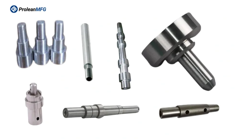
step turned components
Manufacturers use Step turning to produce various types of mechanical components that require distinct-diameter sections along their length, such as bolts, stepped shafts, pulleys, and axles.
The table below outlines industry-specific application examples of step-turn machining:
| Industry | Step Turning Applications |
| Automotive | Crank and camshafts, gear shafts, transmission shafts, axles. |
| Aerospace | Turbine and rotor shafts, landing gear parts, and miniature shafts. |
| Manufacturing | Spindles & drive shafts, arbors, lead screws, and couplings. |
| Heavy Machinery | Hydraulic rods, cylinder & bush shafts, and linkage pins. |
| Electrical | Different shafts for Motors, generators, pumps, & other electrical devices. |
| Tooling | Custom mandrels, guide & ejector pins, forming punches, and die holders |
| Oil & Gas | Heavy tool joints, drill rods, valve stems, and different types of shafts. |
What Are the Advantages of Step Turning Operations?
Faster machining cycles, tight tolerances, reduced heat buildup, cost-effectiveness, and ease in assemblies are the main advantages of step turning operations.
Let’s further break down these advantages:
- Production Speed: As step turning allows for multi-diameter machining in a single setup, it improves production speed.
- Tight Tolerances: It maintains a tolerance of ~ ±0.01 to ±0.05 for each section of the stepped component.
- Cost-Benefit: The reduced setup time and streamlined process reduce machine costs compared to straight-turn operations.
- Easier Assembly: The step turning not only helps produce perfect-fit parts for mechanical assemblies but also ensures the desired interferences.
What Are the Disadvantages of Step Turning?
Step turning also has disadvantages, such as high material waste, limited step size, alignment sensitivity, and shape limitations.
- Material Wastage: Compared to other CNC turning operations, step turning can help to reduce waste from the workpiece when creating multiple sections with distinct diameters in a cylindrical rod.
- Step Size Limitation: The size (diameter) of the largest step is limited to the stock size.
- Alignment Sensitivity: A minor misalignment in tool setup & workpiece clamping results in a significant error in step dimensions.
- Shape Limitation: Step turning cannot machine complex geometrical shapes & features, such as slots and angled surfaces.
What Are the Step Turning Tools?
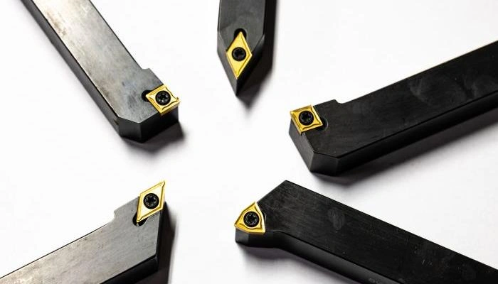
step turning tools
Turning inserts, parting tools, and grooving tools are the common step turning tools. Their selection depends on the complexity, material type, desired precision, and other factors.
Turning Inserts
These are used for heavy machining of the workpiece to achieve a uniform diameter along its length, before making the steps. Replaceable carbide or ceramic inserts are recommended for this.
Parting Tools
These step turning tools can have one, two, or more cutting edges with positive (or neutral) rake angles. These are suitable for forming smooth transitions between two steps. It means you can define the lines (boundaries) for each step that needs to be machined.
Grooving Tools
Sometimes, grooving tools are used in step turning operations to produce shallow steps with sharp corners.
Equipment and Quality Control Instruments Used in CNC Turning Operations
Lathe machines and turning centers are the two common pieces of equipment for CNC turning operations. Subsequently, you also need vernier calipers, micrometers, and other measuring instruments for quality control purposes.
- CNC Turning Center: A CNC turning center can accommodate step-turning and other tools in a power turret to perform multiple operations in a single setup.
- Lathe Machine: You can use either a manual or a CNC lathe, based on desired precision and production volume.
- Vernier Caliper: It helps to measure the thickness of material that needs to be removed after the tool passes to ensure the dimensional accuracy of the steps. Vernier calipers can measure up to two decimals.
- Micrometers: Micrometers provide more accurate measurements of step diameters than Vernier calipers.
Can I Use Any Material in Step Turning?
No! You can perform step turning on diverse materials, but not all of them. It is compatible with metals, plastics, composites, ceramics, etc.
Here is the list of common steps for turning materials.
- Cast iron
- Stainless steels
- Alloy steels
- Tool steels
- Aluminum and its alloys
- Copper
- Brass and bronze
- Titanium alloys
- Plastics (ABS, PC, PEEK, PTFE, etc.)
- Carbon-fiber composites
- Alumina ceramics
Choosing the material for step-turned components depends on multiple factors, such as machinability & capability of available equipment, strength requirement for the application, thermal characteristics, material cost, and specific industry standard.
What are the CNC Turning Defects and How to Prevent Them?
Surface roughness, dimensional Inaccuracies, sharp edges, chatter, taper errors, and built-up edges are the common defects in CNC turning operations.
The table below outlines the causes and prevention strategies for these defects.
| Defect | Causes | Prevention |
| Surface roughness | Tool wear, machine vibration, and high feed rates | Ensure tool sharpness, set the right feed & speed, maintain machine stability |
| Dimensional inaccuracy | Programming error, dull edges, and material stress | Calibrate the machine routinely, stress-relieve blanks, and control shop temperature |
| Sharp edges | High feed, workpiece ductility, and poor exit path | Use sharp cutters, incorporate chamfers, and optimize the tool path |
| Chatter | Loose workpiece clamping, lengthy overhang, and poor setup rigidity | Reduce overhang, firmly clamp the workpiece, reduce cutting depth, and increase setup stiffness |
| Taper errors | Tailstock misalignment, tool deflection | Calibrate the alignment, use live centers, and consider taper compensation |
| Built-up edge (BUE) | Lowe speeds and insufficient lubrication | Increase cutting speed, use coated inserts (TiN/AlTiN), and apply flood coolant. |
What is the Difference between Step Turning and Taper Turning?
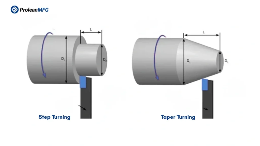
Step turning vs taper turning
Unlike step turning, taper turning produces conical shapes with a steady change in diameter along the length. It is used to produce tapered shafts, pins, and other custom industrial parts. You can perform a step turning operation on a lathe machine with three different methods: tailstock offset, compound rest, and taper attachment.
Another difference is tool movement. The cutter moves parallel to the axis of rotation during step turning, whereas it is diagonal in taper turning.
What is the Difference between Step Turning and Straight Turning?
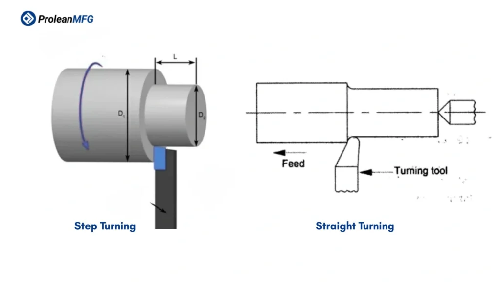
Step turning vs straight turning
Straight turning, also known as cylindrical turning, produces a perfectly cylindrical surface with a consistent diameter throughout the desired length of a workpiece. You can consider turning a single step as straight turning; it means no transitions in diameter.
You can choose straight turning for general purposes, such as workpiece roughing for secondary operations, producing simple cylindrical shafts, and rods.
What is the Difference between Step Turning and Form Turning?
Form turning produces complex and continuous contours/profiles, whereas step turning produces simple cylindrical steps of varying diameters along the workpiece length. It requires specialized form turning tools that can shape chamfers, grooves, irregular profiles, etc.
Some examples of applications of the form-turning process include cam profiles, O-ring grooves, and machinery handles.
Step Turning vs Grooving vs Facing
Step turning, grooving, and facing are performed on a lathe but differ in what they are used for. CNC grooving produces narrow channels or recesses, and facing is typically used for flattening the end face of barstock
The table below compares feed direction, when to use them, and applications.
| Aspect | Step Turning | Grooving | Facing |
| Feed direction | Mostly axial feed | Radial | Perpendicular feed |
| When to use | For multiple diameters along the length | Slots, recesses, or retaining features | End flattening and length correction |
| Applications | Axel & transmission shafts | O-rings, piston rings, retaining clips, etc | End squaring of barstock, bolt end finishing, and cylindrical blanks. |
Step Turning vs Milling vs Drilling
Turning, milling, and drilling are all machining processes, but they differ in how they work, the required tooling, and the shapes and features they can create.
CNC milling uses rotating tools to shape the workpiece into detailed 3D components. It can create intricate contours, profiles, internal channels, cavities, slots, and many other features.
Drilling is a specialized hole machining process. It creates through & blind cylindrical holes of varying sizes on diverse materials. It uses drill bits corresponding to the desired hole diameter. Milling machines can also make holes, but drilling machines are faster and more precise.
Among the three, milling is the most diverse and offers the most extensive machining capabilities.
Pro Design Tips to Reduce Step Turning Costs
Simplifying the design, choosing the right stock size, applying correct dimensions, and avoiding repositioning are some tips to reduce the step turning cost.
- Simplify step geometry and avoid overtolerancing
- Choose the stock that has a size near the highest diameter of the step turning section.
- Consider the type and size of standard toolings while setting dimensions.
- Optimize your design if it has step-turning features requiring repositioning.
- Avoid small and deep holes in the turning design.
Summing Up
Step turning sounds like a simple machining process, but it has extensive uses in modern manufacturing, from simple stepped shafts for bearings to intricate shafts for aircraft turbines and automotive transmission systems.
Saying this, you must create a DFM-optimized design, choose the right equipment and tool, and set the machine correctly for precision step turning. Additionally, material selection, G-code programming, and the expertise of operators also influence the result.
At ProleanMFG, we provide comprehensive CNC Turning Services, covering everything from DFM feedback to surface treatment. Not only can we produce multi-diameter shafts, but we can also produce a wide variety of CNC-turned items, tailored to your specific needs.
FAQs
What is an important step in turning?
Deciding the right cutting sequence is an important step in turning that includes roughing, feature machining, and finishing.
How Accurate Is Step Turning?
Step turning is among the highly accurate machining processes. It provides tolerances as tight as ±0.005 mm, with advanced CNC equipment.