Custom metal & plastic parts

5-axis CNC
machining.

Multi-face features, compound angles and contoured surfaces. Start with the geometry and choose the tool orientation that serves it.

Bring the model and drawing. Review 3+2 positioning or simultaneous motion, fixture clearance and datum transfer before confirming a route.

Cutting tool at an impeller-like metal component held on a tilted rotary fixture; process reference01 / THE PROCESS
From drawing to partOrientation follows the feature.
PROCESSES3+2 / simultaneous route review
MATERIALSMetals & engineering plastics
ORDER STAGESComplex features → Practical route
ACCEPTANCEProfile · position · datum transfer

01 / Geometry before axis count

More directions.
A deliberate process.

Five-axis machining combines three linear directions with two rotary degrees of freedom. Reorienting the tool relative to the workpiece can help reach inclined faces, compound-angle holes and curved surfaces.

The useful question is how to reach each feature while maintaining support and the required relationships. Indexed 3+2 cutting and simultaneous five-axis motion serve different needs. Machine layout and rotary-axis names vary; the options below explain process concepts, not a verified list of installed equipment.

Compare the routes ↓

02 / Route selection

Position to a face.
Or follow a surface.

Choose a route for feature access and total process cost. Confirm the actual machine configuration and control mode during drawing review.

INDEX → HOLD ORIENTATION → CUT01 / CONCEPT ONLY · NOT A REAL TOOLPATH

3+2 positioning

Orient the part or tool with two rotary axes, then machine a region with that orientation held. Index to another position for a different face.

Geometry to review
Angled bores, inclined mounting faces and multi-face prismatic parts.
Route check
Plan safe retracts between orientations and verify each face is clear of the fixture.
Review access & cost ↓
ORIENTATION CHANGES DURING CUT02 / CONCEPT ONLY · NOT A REAL TOOLPATH

Simultaneous five-axis

Linear and rotary motion are coordinated during cutting so the tool direction can change along a surface. Not every cut needs all five axes moving.

Geometry to review
Freeform surfaces and curved regions that benefit from continuous orientation changes.
Route check
Review holder clearance, rotary travel, cutting contact and transitions; validate the intended strategy.
Review access & cost ↓
OPEN ACCESS / FIXED DIRECTION03 / CONCEPT ONLY · NOT A REAL TOOLPATH

When three axes suffice

Open pockets, planar faces and holes with straightforward access may be more economical on a three-axis route, even with a simple additional setup.

Geometry to review
Parts whose geometry does not justify rotary access or complex programming.
Route check
Compare total setup, programming, cycle and inspection costs at the required quantity.
Review access & cost ↓

Process distinction reference: Haas five-axis machining overview ↗. General explanation only; no Haas equipment ownership is implied.

03 / Specifications & acceptance

Specify relationships.
Not just dimensions.

Use a controlled drawing to identify critical features. Confirm individual tolerances against geometry, material, workholding and measurement requirements.

Complex-part RFQ and acceptance checklist
RequirementSpecify in the RFQManufacturing implication
Usable envelope & accessOverall stock/part size, inclined reach, fixture contact and swept volume during rotation.Nominal travels alone do not establish usable capacity; tools, holders and fixtures consume space.
Surface definitionControlled CAD surface revision, profile tolerance, texture and permitted witness/transition marks.A smooth-looking model does not specify acceptance; connect surface controls to functional datums.
Angular features & datumsAngles, hole axes, true position and relationships across faces. Identify datum transfer between setups.Locating and rotary positioning errors remain relevant even if reclamping is reduced.
Deep regions & undercutsOpening width, depth, local radii and hidden faces; identify features without direct access.Tilting may improve reach but cannot make every undercut accessible or eliminate holder collision.
Material & stabilityExact grade, condition, thin sections and heat treatment sequence.Stock removal and unclamping can change the part; review support and final measurement condition.
Final condition & recordsFits after coating, masking, critical surface checks and report/sampling scope.Agree inspection access and measurement strategy, including surfaces difficult to probe.
i

Resolve drawing notes before cutting. State units, revision and the complete general tolerance standard and class. Identify which dimensions apply after heat treatment or finishing, and how flexible parts should be supported during measurement.

04 / Materials for complex geometry

Select the grade.
Plan the stock removal.

A shortlist for five-axis route review. Grade, condition, geometry and required documentation are reviewed for each quote; this list does not indicate stocked inventory.

Material library ↗
METAL / ROUTE REVIEW

Aluminum

6061 · 7075

Lightweight housings and contoured bodies. Review temper, residual stress and distortion as material is removed from several directions.

Confirm for this drawingTemper · wall stability · anodizing
METAL / ROUTE REVIEW

Stainless steel

304 · 316L · 17-4PH

Complex corrosion-resistant components. Heat, work hardening and tool reach affect cutting strategy; confirm the required condition.

Confirm for this drawingGrade / condition · tool contact · passivation
METAL / ROUTE REVIEW

Titanium

Grade and condition to confirm

Weight-sensitive complex geometries can justify titanium review. Cutting heat, rigidity and long-tool access need careful planning.

Confirm for this drawingGrade · stock sourcing · finishing compatibility
METAL / ROUTE REVIEW

Alloy & tool steel

Exact grade / hardness to review

Contoured tooling and fixtures. Define heat treatment sequence and whether final cutting follows hardening.

Confirm for this drawingHardness · distortion · final inspection
POLYMER / ROUTE REVIEW

POM / acetal

Exact grade to review

Complex guides and prototype bodies. Clamping deformation and temperature can influence dimensional acceptance.

Confirm for this drawingPolymer grade · support · inspection condition
POLYMER / ROUTE REVIEW

PEEK

Unfilled / filled grade to review

Technical polymer geometries need grade-specific review. Fillers, thin sections and heat affect machining and surface requirements.

Confirm for this drawingFillers · wall support · end-use conditions

Exact grade, condition and availability are confirmed during quotation.

05 / Finishing complex surfaces

Protect the surface.
Preserve the fit.

Finishing follows the function of each face. Map cosmetic zones, mating features and masked areas on the drawing before the route is quoted.

Explore surface finishing ↗
01

As-machined & deburred

Specify roughness and tool-mark limits on curved faces, plus permitted transition marks between orientations. Define edge breaks at angled-hole intersections and restricted deburring zones.

02

Bead blasting & anodizing

For aluminum parts, agree texture and cosmetic boundaries across compound surfaces. Blasting changes appearance; anodizing changes final dimensions. Define masked bores, threads and datum faces.

03

Passivation, plating & coatings

Choose a treatment compatible with the alloy and environment. Confirm thickness, coverage and the final acceptance condition; narrow pockets and hidden faces may need special review.

04

Polishing & functional interfaces

For sculpted surfaces, identify where polishing may change a controlled profile or round an edge. Agree texture direction, allowance and acceptance after finishing; gloss does not establish profile accuracy.

06 / Quality & inspection

Make the requirements clear.
Make the checks meaningful.

For multi-face and contoured parts, relate surface profiles and angled features to the drawing datums. Confirm measurement access and datum alignment before accepting the machining route.

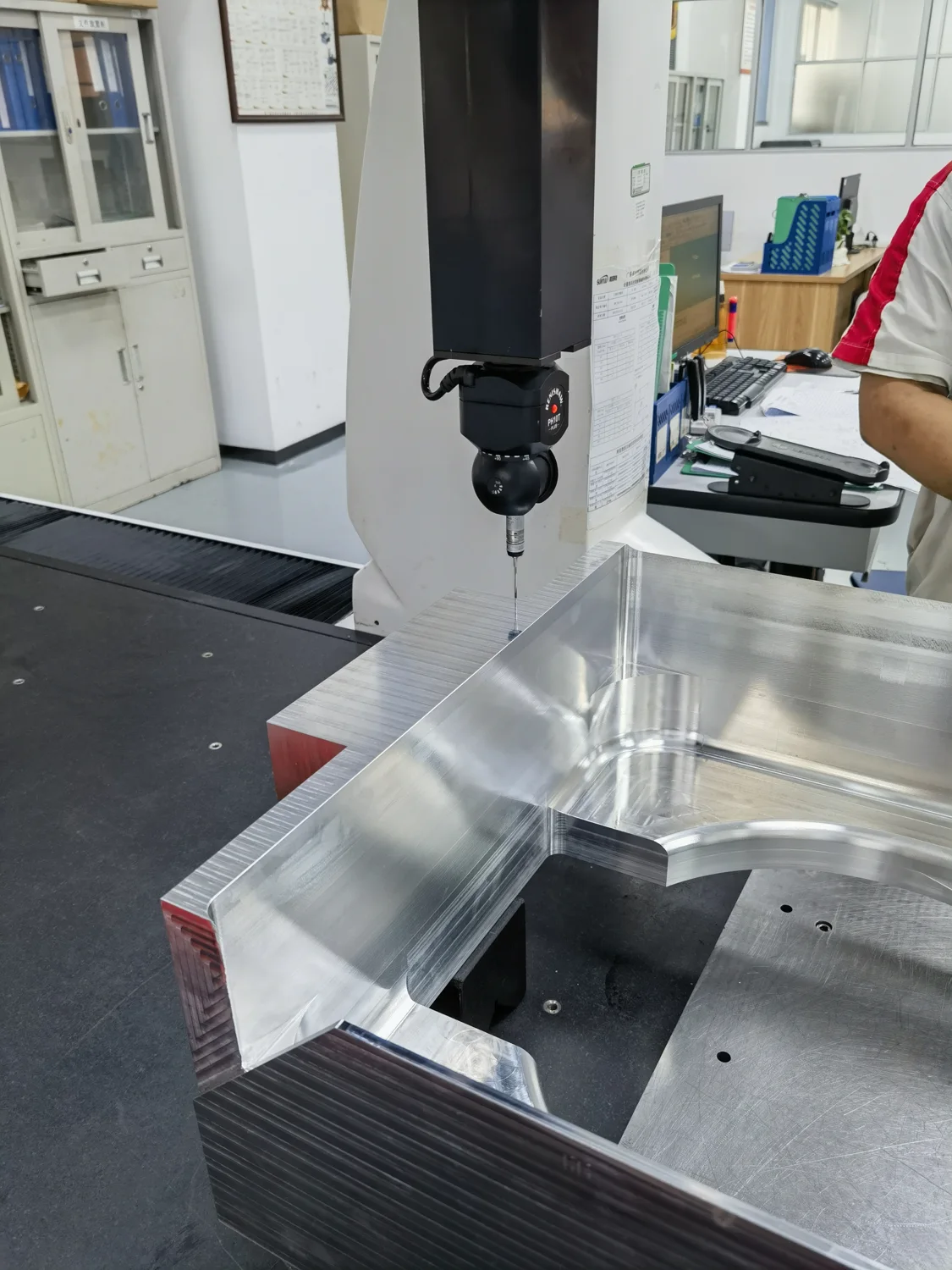
Touch probe measuring features on a machined metal part
Dimensional inspectionCheck the feature. Reference the drawing.
  1. 01

    Agree the acceptance plan

    Confirm the CAD revision, datum setup, angular hole relationships and controlled surface profiles. Define support and the measurement condition after unclamping and finishing.

  2. 02

    Match the check to the characteristic

    Plan measurement access to inclined holes and freeform surfaces. Agree datum alignment, sampling of surface points and the reporting method. Visual appearance alone does not establish profile, position or surface roughness acceptance.

  3. 03

    Define the records you need

    Identify critical features for first-article review and any batch sampling, material records or post-finish reports needed. Confirm document scope and traceability in the quotation.

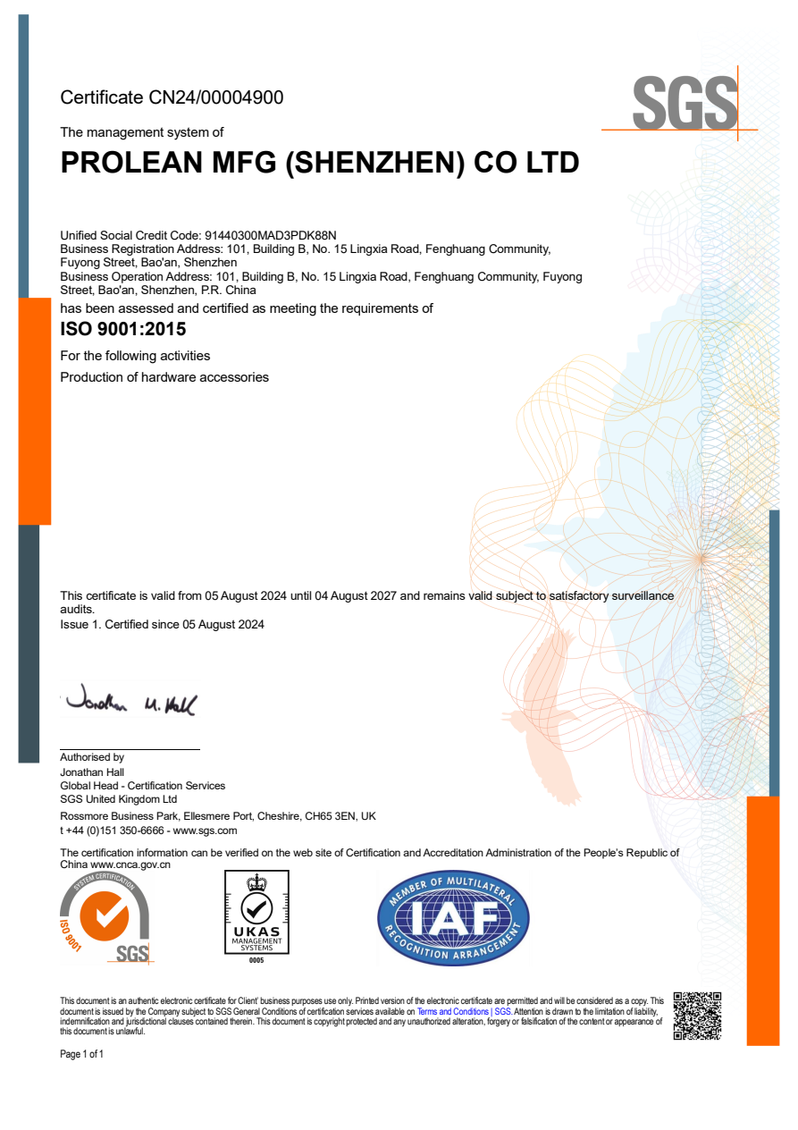
SGS ISO 9001:2015 certificate for PROLEAN MFG (SHENZHEN) CO LTD
Documented quality management

ISO 9001:2015

PROLEAN MFG (SHENZHEN) CO LTD
SGS · CN24/00004900

Scope: Production of hardware accessories.
View original certificate ↗

Certificate dates: 05 Aug 2024–04 Aug 2027, subject to satisfactory surveillance audits. Certification concerns the management system; part acceptance follows the agreed specification.

Explore our quality & inspection approach ↗

07 / Five-axis DFM & cost

Reach is a system.
Not just a tool tip.

Review the part, holder, fixture and rotation together. These concepts support drawing review; they do not represent a proven machining program.

HOLDER + CUTTER / SWEPT CLEARANCENEARBY WALLCLAMPA / LOCATING DATUMREGRIP → REVIEW DATUM TRANSFERIllustrative clearance / not a real toolpath

Orient → clear → support → inspect.

Tool reach & collision clearance

Review the cutter, shank, holder, spindle and fixture as an assembly. A tool tip may reach a feature while its holder collides with a nearby wall. Tilt can shorten required overhang, but the feasible angle depends on all surrounding geometry and rotary travel.

3+2 or continuous motion?

For discrete inclined faces, indexing then cutting at a fixed orientation may be sufficient. A curved region may benefit from changing orientation during the cut. Ask which surfaces need continuous motion and which do not; complexity should solve an access or surface requirement.

Workholding & the hidden underside

Reserve stable clamping faces or discuss sacrificial stock and tabs. The surface used to hold the part is usually not freely accessible. Release, regrip or separate operations may still be needed, with enough material and support to preserve the finished geometry.

Datum transfer & angular relationships

Define datums by how the component locates in assembly. Identify features related across tilted positions and later setups. Fewer reclamps can reduce one source of variation, but fixture location, rotary alignment, tool deflection and measurement still affect the result.

Freeform surfaces, walls & edges

Specify surface profile and texture independently. Check local curvature against cutter access, thin-wall support and transitions between tool orientations. Show sharp-edge restrictions and the final condition after polishing or coating.

When five axes earn their cost

Compare programming and validation, workholding, machine time, finishing, inspection and quantity. A multi-face part may avoid repeated fixtures; a simple open pocket may remain cheaper on three axes. Compare the complete route rather than assuming more axes always save money.

08 / Geometry & applications

Complex shape.
Specific questions.

Typical geometry references for route selection. No customer-project results, industry certification or end-use validation are implied.

Multi-face assemblies

Angled brackets
& housings

Relate inclined mounting faces and compound-angle bores to functional datums. Check whether indexing can reach each region without fixture interference.

Define early
Position · angle · clamping faces
Review acceptance ↑
Contoured components

Flow-path surfaces
& sculpted bodies

Review curvature, cutter access, surface profile and transition marks. An impeller-like shape is a geometry example, without an application qualification claim.

Define early
Surface model · profile · texture
Review acceptance ↑
Tooling & development

Contoured fixtures
& prototype forms

Define contact surfaces, inspection alignment and heat treatment. Confirm whether a three-axis finishing route already provides sufficient access.

Define early
Material condition · contact · quantity
Review acceptance ↑

For regulated or safety-critical parts, provide the applicable qualification, traceability and validation requirements for specific review.

09 / Prototype to production

A clear path from
RFQ to repeat order.

Complex-part prototypes and repeats need a controlled surface model, drawing and agreed setup plan. Share current quantities, likely repeat demand and any first-article approval gate.

  1. 01 / SHARE

    Send the requirements

    Send the surface model and drawing with datums, compound angles, profile controls, material condition and finish. Include quantities, inspection records and your target date.

  2. 02 / REVIEW

    Resolve the details

    Resolve indexed versus simultaneous cutting, holder clearance, workholding, datum transfer and finish allowances. Confirm price, documentation and manufacturing lead time for the agreed route.

  3. 03 / CONFIRM

    Align before cutting

    Freeze the revision and acceptance plan. Agree sample or first-article approval, material requirements and any finishing masks before machining starts.

  4. 04 / DELIVER

    Inspect & plan the next run

    Complete agreed dimensional and surface checks. Protect machined edges and faces in packaging. For repeats, reconfirm revision, stock condition and changed demand.

For procurement teams

Ask for pricing at your planned quantities and clarify material documents, inspection scope, packaging, freight and delivery terms. This makes supplier comparisons more useful than a unit price alone.

10 / Five-axis FAQs

Before you
send the drawing.

Practical answers for engineers,
buyers and manufacturing teams.

Ask a project-specific question ↗
What is the difference between 3+2 and simultaneous five-axis machining?

In 3+2 machining, two rotary axes orient the workpiece or tool and hold that orientation while a region is cut. Simultaneous five-axis machining coordinates rotary and linear motion during cutting, allowing the tool direction to vary along a surface. The suitable route and available control mode require part-specific confirmation.

When is five-axis machining worth considering?

Consider it when compound angles, multiple faces or curved surfaces create difficult tool access or repeated fixtures. Compare the entire process, including programming, verification and inspection. Straightforward open geometry may remain more economical on three axes.

Can every feature be completed in one setup?

No. Clamping faces, hidden regions, reach limits and finishing may require release, regripping or separate operations. Identify datum transfer and the final underside requirements before assuming a single setup.

Does five-axis automatically mean tighter tolerances?

No. Extra orientation can reduce some reclamping needs, but machine alignment, workholding, material stability, tool deflection and measurement still matter. Specify the critical feature and datum relationship; confirm achievable limits for the actual drawing.

What limits tool access and part size?

The relevant envelope includes the stock, fixture and tool/holder assembly throughout rotation. Rotary travel, surrounding walls, clearance and support all matter. No universal part-size limit is claimed here; submit CAD for review.

Can five-axis machining reach any undercut?

No. A tilted approach may reach some regions, but the cutter and holder still need a collision-free path. Fully enclosed or hidden features may require redesign or a separate process. Show them explicitly in the model and section views.

What files are needed for a complex-part quote?

Send STEP/STP or IGES with a controlled PDF drawing. Include revision, datums, profile and angular requirements, material condition, quantities, surface finish, inspection records and your target date. Clarify any NDA before sharing files.

How are cost and manufacturing lead time confirmed?

Material sourcing, programming, collision review, fixtures, cutting, finishing and inspection influence the route. Provide quantity breaks and approval gates. Quote response time and manufacturing lead time are separate; both need order-specific confirmation.

Scroll to Top