Custom metal & plastic parts

CNC turning
services.

Shafts, sleeves, bushings and fittings. Custom turned metal and plastic parts built around the diameters, faces and threads that make the assembly work.

Bring the drawing. Review OD and ID relationships, runout, workholding and secondary features before confirming the turning route.

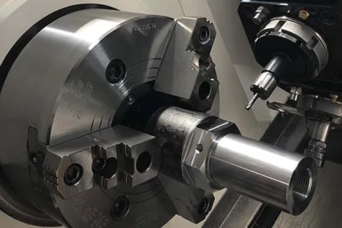
Lathe chuck holding a cylindrical component with an internal thread, beside a cutting tool01 / THE PROCESS
From drawing to partRotating geometry. Functional relationships.
PROCESSESOD · ID · grooves · threads
MATERIALSMetals & engineering plastics
ORDER STAGESPrototype → Repeat batches
ACCEPTANCEFits · runout · inspection

01 / Geometry around an axis

Start with the axis.
Define what must align.

CNC turning removes material from a rotating workpiece to form outside diameters, bores, shoulders, grooves and threads. It is a practical starting point for shafts, sleeves, bushings, spacers and fittings.

Diameter alone does not define the job. Length, unsupported sections, bore depth, grip surfaces and the relationship between features determine the setup. Cross holes, wrench flats and off-axis details may add milling or drilling operations.

Review your turned-part design ↓

02 / Turning route selection

Round features.
A considered setup.

Review the dominant geometry and its critical relationships. The final route may combine turning with support, a second setup or off-axis operations.

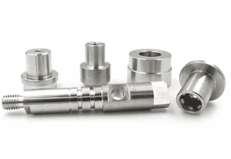
Stepped metal shafts and sleeves, including a cross hole, external thread and flanged bore01 / ROTATIONAL PARTS

OD turning & facing

Create stepped diameters, shoulders, tapers and end faces around the rotational axis. Features machined together can share a setup; reclamping still needs datum control.

Typical geometry
Shafts, spacers, flanges and stepped components.
Setup check
Define grip length, shoulder radii, axial stops and any surface that must remain free of chuck marks.
Define the requirements ↓
BORE DEPTH / ACCESSSECTION / NOT A PRODUCTION DRAWING02 / INTERNAL FEATURES · ILLUSTRATION

Boring, grooves & threads

Internal diameters and recesses require space for the tool and chips. Blind bores and internal threads need clear depth and bottom geometry definitions.

Typical geometry
Sleeves, bushings, threaded ports and fittings.
Setup check
Separate full usable bore or thread depth from tool clearance; identify undercuts and burr-sensitive intersections.
Define the requirements ↓
CROSS HOLEFLATSOFF-AXIS FEATURES / REVIEW ROUTE03 / SECONDARY ACCESS · ILLUSTRATION

Secondary features & support

Cross holes, flats and off-axis pockets require a suitable additional approach. Live-tool or separate-machine routes must be confirmed for the part.

Typical geometry
Couplers, connectors and shafts with non-round details.
Setup check
Review angular orientation, datum transfer and slender-part support; do not assume all features finish in one setup.
Define the requirements ↓

03 / Specifications & acceptance

Diameter is a start.
Relationships make the part.

Identify which surfaces locate, rotate, slide or seal. Agree feature-specific acceptance against material, support, tool access and the final surface condition.

Turned-part RFQ and acceptance checklist
RequirementSpecify in the RFQManufacturing implication
Diameter, length & stockMaximum OD, overall length, bar or blank condition, grip allowance and thin sections.Chuck clearance, supported length and tool access determine usable capacity; a milling X/Y/Z envelope does not define turning limits.
Datum axis & runoutDatum features and functional axial or radial runout controls; identify measurement condition.A diameter limit does not control runout. Agree setup and measurement from the functional datum axis.
OD/ID fits & shouldersLimits or fit designation, bore depth, shoulder location, squareness and mating radii.Relates sliding or bearing fits to seating faces; thin sleeves can distort under gripping loads.
Grooves & threadsWidth, depth and root radius; thread standard, pitch, class, usable length and blind/through condition.Tool width, runout and bottom clearance affect access; thread engagement differs from drill depth.
Cross holes & flatsPosition, angle to other features, burr limits and intersections with internal passages.May add indexed or separate operations. Define how secondary features reference turned datums.
Surface & final recordsRa on sealing or bearing lands, coating masks, final dimensions and inspection/report scope.Finishing and heat treatment can change fits. Confirm any grinding or special testing as separate operations.
i

Define the final condition. State units, revision and complete general tolerance standard/class. Mark dimensions after heat treatment or coating, and how a flexible shaft or sleeve should be supported during measurement.

04 / Materials for turned parts

Choose the grade.
Review the bar condition.

A turning-focused shortlist for quotation review. Grade, heat treatment, stock form and straightness affect the route; listed materials do not indicate inventory or confirmed availability.

Material library ↗
AL / METAL

Aluminum

6061 · 7075

Lightweight spacers, sleeves and couplers. Thin sections and a deep bore need a gripping plan that limits distortion.

Review for turningAlloy / temper · wall section · anodizing masks
FE / METAL

Stainless steel

303 · 304 · 316L · 17-4PH

Shafts, fittings and corrosion-resistant sleeves. Grade and heat-treatment condition change cutting behavior and finishing choices.

Review for turningGrade / condition · threads · passivation
FE / METAL

Carbon & alloy steel

1018 · 1045 · 4140

Loaded shafts, pins and wear interfaces. Plan machining around heat treatment and identify any final grinding requirement.

Review for turningHardness · straightness · final fits
CU / METAL

Brass & copper

Exact alloy to review

Bushings, fittings and conductive contacts. Specify alloy, service environment and burr limits at small ports.

Review for turningAlloy / lead restrictions · contact finish
POM / PLASTIC

POM / acetal

Exact grade to review

Low-friction sleeves, spacers and insulating components. Clamping load and inspection temperature can change measured fit.

Review for turningGrade · OD/ID stability · use temperature
PA / PEEK / PLASTIC

Nylon & PEEK

Unfilled / filled grade to review

Functional bushings and insulating parts. Nylon moisture conditioning and polymer filler content affect dimensional planning.

Review for turningConditioning · filler · service environment

Exact grades, condition and availability require quotation review.

05 / Finishing turned geometry

Protect the surface.
Preserve the diameter.

Map bearing lands, sealing diameters, thread flanks and cosmetic zones separately. Define whether each size applies before or after treatment.

Explore surface finishing ↗
01

As-turned & deburred

Turning leaves directional tool marks. State roughness and texture needs on functional lands, edge breaks and allowable burrs at grooves, cross holes and thread starts.

02

Anodizing & cosmetic texture

For aluminum, define color, texture and handling zones. Review dimensional growth and masking on bearing diameters, bores, threads and electrical contact areas.

03

Passivation, plating & coatings

Match treatment to alloy and environment. Thickness changes OD and ID differently; specify final fit acceptance and review coverage in blind bores or narrow grooves.

04

Polishing & final sizing

Identify sealing and sliding surfaces requiring special texture or sizing. Grinding, honing or polishing must be reviewed as additional operations; turning alone does not imply them.

06 / Quality & inspection

Make the requirements clear.
Make the checks meaningful.

For turned parts, agree how OD, ID, shoulders and secondary features reference the datum axis. A dimensional report must address the characteristics that govern assembly.

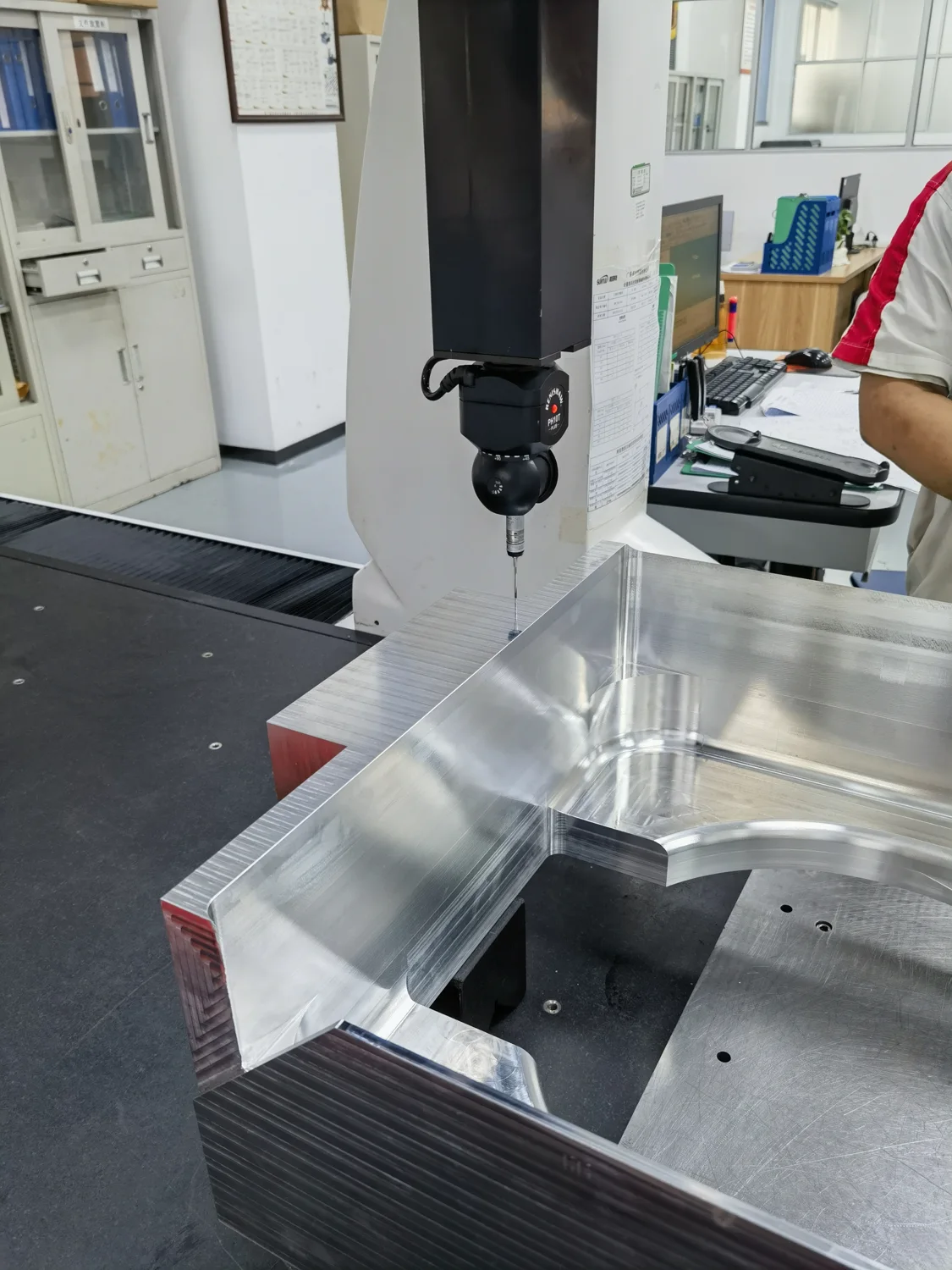
Touch probe measuring features on a machined metal part
Dimensional inspectionInspection reference. Agree the method for each feature.
  1. 01

    Agree the acceptance plan

    Confirm the revision, datum axis, fits, shoulder locations and runout requirements. Define support and gripping conditions for slender shafts and thin sleeves.

  2. 02

    Match the check to the characteristic

    Match size, form, runout and thread checks to the drawing. Agree the method and access for internal features; diameter measurement alone does not establish roundness or axis relationships.

  3. 03

    Define the records you need

    Identify critical features for first-article review and any batch sampling, material records or post-finish reports needed. Confirm document scope and traceability in the quotation.

SGS ISO 9001:2015 certificate for PROLEAN MFG (SHENZHEN) CO LTD
Documented quality management

ISO 9001:2015

PROLEAN MFG (SHENZHEN) CO LTD
SGS · CN24/00004900

Scope: Production of hardware accessories.
View original certificate ↗

Certificate dates: 05 Aug 2024–04 Aug 2027, subject to satisfactory surveillance audits. Certification concerns the management system; part acceptance follows the agreed specification.

Explore our quality & inspection approach ↗

07 / Turning DFM & cost guidance

Resolve the details
before they become rework.

These design checks help prepare a useful manufacturing conversation. Final dimensions and process decisions depend on the part’s function and geometry.

Turned shaft section illustrating datum axis, shoulder, bore, groove and support reviewSHOULDER / ROOT RADIUSID / BLIND DEPTHGROOVE ACCESSOVERALL LENGTH / SUPPORT REVIEWBORE / THREADDATUM AAXIS RELATIONSHIP / RUNOUTSECTION SKETCH · NOT TO SCALEDesign review / illustrative geometry

Function → feature → process → inspection.

Slender shafts & unsupported length

Review length-to-diameter relationship, cutting loads, stock straightness and the surfaces available for a center or other support. A tailstock or steady support may help but affects access and setup. Confirm the strategy before specifying tight runout over a long span; there is no universal safe slenderness ratio.

OD/ID relationships & thin sleeves

Specify the functional fit and datum axis rather than treating each diameter independently. Thin walls can spring under chuck pressure and change size after release. Agree clamping, stock removal sequence and the free-state measurement condition.

Shoulders, grooves & root radii

Show the mating component and any needed relief. A shoulder root radius can interfere with a sharp mating edge; very narrow or deep grooves restrict tool rigidity and chip removal. Use standard groove forms where function permits and identify burr-sensitive edges.

Blind bores & usable threads

State bore depth, bottom shape, thread standard, pitch/class and full usable engagement. Distinguish usable thread from drill depth and tool runout space. Deep internal features limit tool stiffness and chip evacuation; do not imply a full thread to a flat blind floor.

Cross holes, flats & datum transfer

Define angular position and how off-axis features relate to the turned axis and shoulders. Review live-tool versus separate operations without assuming installed machine configuration. Cross-hole burrs inside a bore may need explicit access and inspection.

Cost, finish & quantity breaks

Cost follows material/blank size, stock removal, supports, setups, secondary features, finish and inspection. Concentrate tight controls on functional surfaces. Quote quantity breaks, mask fits where needed and confirm final dimensions after heat treatment or coating.

08 / Parts & applications

The application
changes the questions.

Typical turned-part geometries and the requirements they raise. These examples are design references, without customer attribution or application-specific qualification claims.

Motion & automation

Stepped shafts
& pins

Relate bearing lands and locating shoulders to the working axis. Review runout over the supported span and cross-hole orientation.

Define early
Fits · runout · support
Review the checklist ↑
Sliding & wear interfaces

Sleeves
& bushings

Relate OD location to the functional bore. Define wall thickness, clearance, free-state inspection and any finishing allowance.

Define early
OD/ID relationship · wear · conditioning
Review the checklist ↑
Fluid & assembly interfaces

Threaded fittings
& couplers

Define thread form, sealing lands, port depth and wrench flats. Pressure or leak testing requires separate agreement.

Define early
Thread class · seals · internal burrs
Review the checklist ↑

For regulated or safety-critical applications, provide the applicable standards, traceability and validation requirements. Project suitability and documentation require specific review.

09 / Prototype to production

A clear path from
RFQ to repeat order.

Prototype and repeat turning need a controlled revision and an agreed setup plan. Share current quantities, likely repeat demand and any first-article approval gate.

  1. 01 / SHARE

    Send the requirements

    Send CAD and a drawing with datum axis, OD/ID fits, runout, usable threads, material condition and finish. Include quantities, inspection records and your target date.

  2. 02 / REVIEW

    Resolve the details

    Resolve gripping, slender-part support, secondary access, datum transfer and finish allowances. Confirm price, documentation and manufacturing lead time for the agreed route.

  3. 03 / CONFIRM

    Align before cutting

    Freeze the revision and acceptance plan. Agree sample or first-article approval, material requirements and any finishing masks before machining starts.

  4. 04 / DELIVER

    Inspect & plan the next run

    Complete agreed dimensional and surface checks. Protect machined edges and faces in packaging. For repeats, reconfirm revision, stock condition and changed demand.

For procurement teams

Ask for pricing at your planned quantities and clarify material documents, inspection scope, packaging, freight and delivery terms. This makes supplier comparisons more useful than a unit price alone.

10 / CNC turning FAQs

Before you
send the drawing.

Practical answers for engineers,
buyers and manufacturing teams.

Ask a project-specific question ↗
Which parts are suited to CNC turning?

Parts dominated by rotational geometry: shafts, sleeves, bushings, spacers, fittings and flanges. OD, ID, steps, grooves and axial threads suit turning. Flat-sided bodies or substantial off-axis geometry may justify milling or a combined route.

How do I specify diameters, fits and runout?

Give diameter limits or the required fit designation, identify the datum axis and apply the appropriate geometric control to functional surfaces. Size, roundness and runout describe different requirements. State whether inspection is free-state or supported and whether values apply after finishing.

Can turned parts include cross holes or flats?

Yes, these features can be considered with additional drilling or milling access. The route may use suitable live tooling or a separate setup, subject to review. Specify their position and angular relationship to the turned datums, plus burr limits at internal intersections.

When should I consider Swiss turning?

Review Swiss turning for small, slender parts where guide-bushing support near the cut may help. Bar diameter, condition, straightness, feature layout and quantity matter. Conventional turning may suit other chucking and support needs; neither route automatically eliminates secondary work.

What drawing information is needed for threads and blind bores?

Specify internal or external thread, standard, size, pitch, class and full usable length. For blind features, distinguish usable bore/thread depth from drill depth, bottom form and runout clearance. Identify sealing requirements, thread gauges and intersecting ports.

How do material and quantity affect price?

Alloy and condition affect stock sourcing, cutting and finishing. Diameter, unsupported length, deep bores, secondary features and inspection can add operations. Setup effort spreads differently across batches; share prototype and repeat quantity breaks for a meaningful comparison.

What diameter, length and tolerance can be confirmed?

Send the maximum OD, overall length, bore depths, stock condition and critical controls. Usable capacity depends on chucking, support, tool reach and measurement, not a generic milling envelope. Tolerances and any special sizing operation require drawing-based confirmation.

How are finishing and delivery requirements agreed?

Mark final-state fits, masking, surface texture and documentation. Material sourcing, supports, secondary operations, finishing and inspection affect manufacturing lead time. Share your target date and approval gates; quote response time is separate from production time.
Scroll to Top