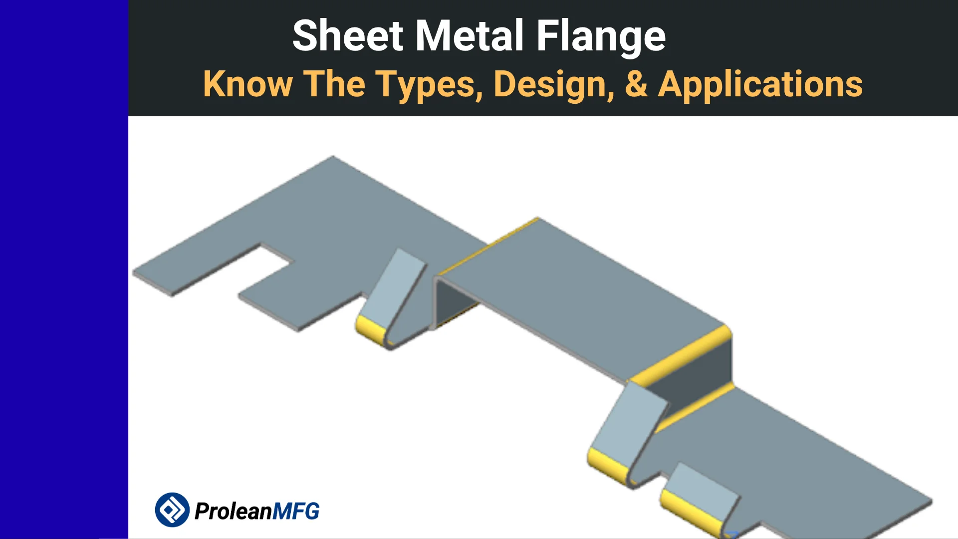
A sheet metal flange is a bent edge that stiffens a part or provides a surface for joining it to another component. In sheet metal bending design, the flange geometry is matched to the material, tooling, and assembly.
This feature can determine the rigidity or tightness of an assembly. Whether it stiffens a car panel, connects a motor to a frame, or joins two components, the flange plays critical alignment, connection, and load-carrying functions.
A flange may appear simple, but it requires proper design steps that consider springback, cracking, and material wastage. Without compliance with standards and specifications, components can fail to fit and be misaligned, leading to expensive rework.
Key Takeaways
- A sheet metal flange is a bent edge that stiffens the part or provides a joining surface. A hem also folds the exposed edge back.
- Use 4 times the sheet thickness as a starting estimate for flange length. Confirm the actual minimum with the selected press brake tooling.
- The main types of flanges are hemmed, joggled, stretch, straight, and shrink flanges
- 6061-T6 aluminum and some stainless grades can need a larger inside bend radius to prevent cracking. Check springback separately on a trial bend.
What is a Flange in Sheet Metal?
A flange is the portion of a sheet that extends past a bend line. Its face can stiffen the part or provide a surface for a fastener, weld, or mating component.
A flange can follow a straight or curved bend line. When the design calls for a covered edge, a hem folds the raw edge back toward the sheet.
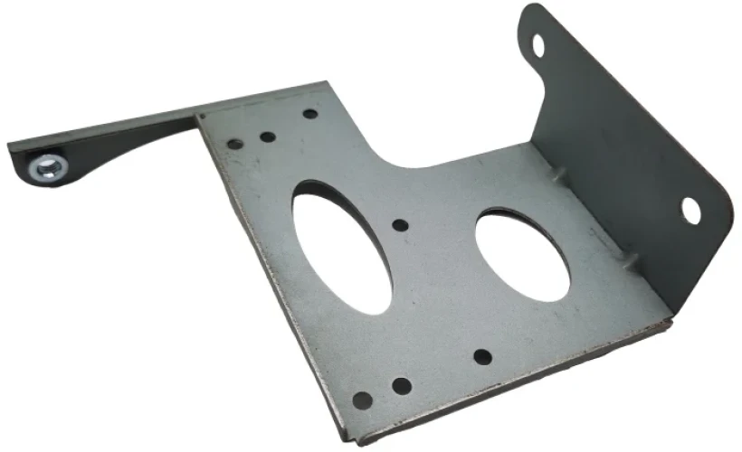
A sheet metal flange
Features of a Sheet Metal Flange
Four key features define a sheet metal flange: Bend line, flange face, flange height/length, and bolt holes.
Bend line: Line along which the sheet metal folds. It separates the main body and the flange.
Flange face: Surface of the bent section. The surface allows for welding, fastening, or mating with other parts.
Flange height/length: Distance between the free edge and the bend. It determines the space for welds and fasteners. The press brake tooling sets the minimum formable length. Flange length also affects the component’s stiffness.
Bolt holes: The flange also has holes for rivets, bolts, or screws. Design limits are used to ensure these holes don’t distort the flange.
Types of Flanges
Common flange types include straight flanges, curved and contoured flanges, stretch flanges, shrink flanges, joggled flanges, and hemmed flanges. Each differs in properties such as stiffness and ideal applications.
Straight Flange
A straight flange is characterized by a straight bend, often at 90°. It is the simplest and most cost-effective type. Manufacturers typically produce a straight flange on a press brake.
Contoured Flange
If a flange is not the straight type, then it is a contoured flange. The bending line for such a flange is curved. The deformation is three-dimensional. Stretch and shrink flanges are perfect examples of contoured flanges.
Stretch Flange
For this contoured flange, the curvature is concave. The material forming the flange is stretched; hence this name. A perfect example of this stretching is the production of a flange for a hole.
Shrink Flange
The curvature in a shrink flange is convex. In producing this flange, the metal used must be shortened or shrunk in size. This concept is easily demonstrated in a flange for a circular cake pan. The finished flange has a diameter that is smaller than the diameter of the original disk.
Joggled Flange
A joggle flange incorporates a small joggle or offset. This feature helps in overlapping or flushing with a second part.
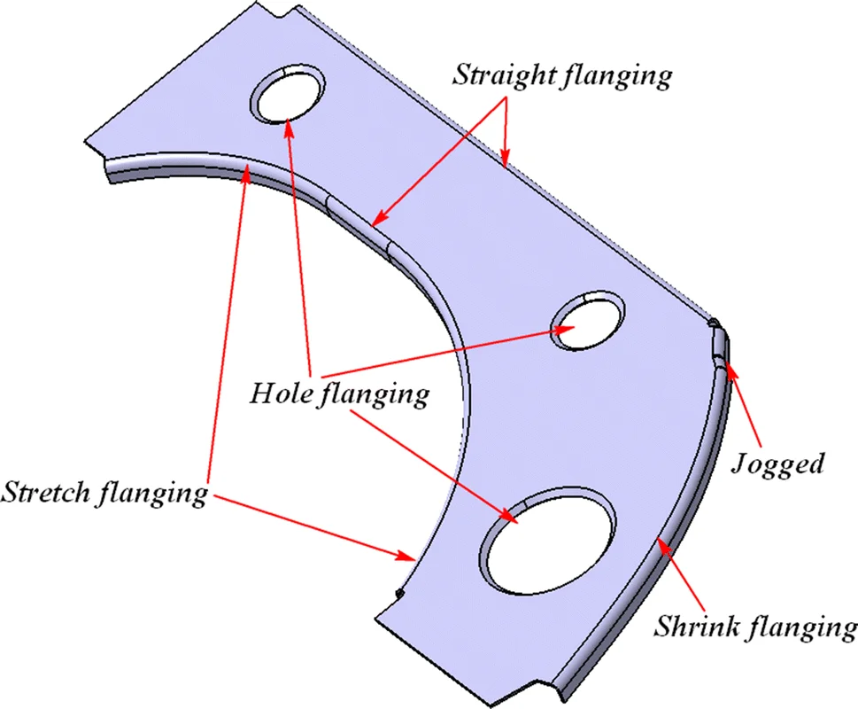
Straight, stretch, joggled and shrink flanges
Hemmed Flange
In a sheet metal hem, the edge is folded back on itself. The hemmed flange is stiffer and safer than an unfolded edge. Common applications of hems are duct edges, enclosure doors, and panels.
Some of the most prominent hem styles are closed (flat), open, teardrop, and rolled hem flanges.
- Closed (flat): The return is pressed flat against the sheet.
- Open: A gap remains between the folded layers.
- Teardrop: The folded edge has a rounded pocket and a narrow opening.
- Rolled: The edge curls into a rounded profile, often used on housings and trim.
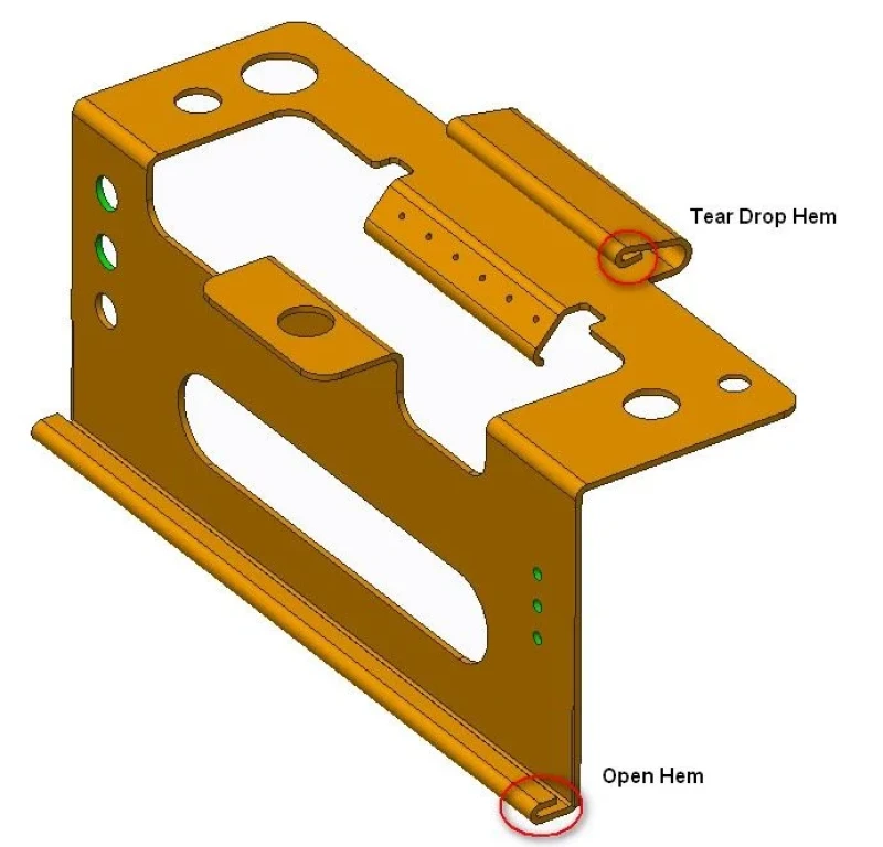
Open hem and teardrop hem
- For an open hem, start with a return length of about 4 times the sheet thickness.
- For a closed hem, start with a return length of about 6 times the sheet thickness. For a teardrop hem, start with a return length of about 4 times the thickness and an inside diameter of about one sheet thickness.
- Confirm the return length and bend geometry with the hemming tool. For 6061-T6 aluminum or harder stainless grades, consider an open or teardrop hem and check for cracking on a trial part.
Flange Chart
Here’s a flange chart summarizing the types of flanges, shapes, and common applications.
| Flange type | Shape | Best application |
| Straight | Straight bend line, usually at 90° | Enclosures, brackets |
| Shrink | Convex curved bend line | Rounded panel edges |
| Stretch | Concave curved bend line | Flanges around cutouts and holes |
| Hemmed | Edge folded back on itself | Edges on ducts, doors, panels |
| Joggled | Small offset in the flange | Flush mating parts and lap joints |
Different Materials for Sheet Metal Flanges
The most common sheet metal flange materials are copper & brass, aluminum alloys, stainless steel, and mild steel. Manufacturers choose a material based on requirements for conductivity, corrosion resistance, strength, weight, and cost.
Sheet Copper & Brass Flanges
Copper is an excellent thermal and electrical conductor. Brass performance depends on the zinc content. Tight bends can be undesirable for brass flanges due to cracking.
Copper and brass sheet flanges are common in jewelry, electrical, and plumbing applications.
Sheet Aluminum Alloy Flanges
Sheet aluminum alloy flanges are used where low weight and corrosion resistance are key requirements. A common choice is alloy 5052, mostly for its excellent forming capability.
A stronger option is alloy 6061-T6, but it is prone to cracking. An adequate bend radius can be used to work around this challenge.
Sheet Stainless Steel Flanges
Stainless steel flanges are useful for their hygiene and corrosion performance. Since they are prone to springback and work hardening, a generous bend radius and bend force are recommended.
Sheet Mild Steel/Low Carbon Steel Flanges
Although mild steel flanges present poor corrosion performance, they are strong, affordable, and easy to produce. You can paint, plate, or galvanize the flange to improve corrosion resistance.
What is a Metal Flange Used For? – Industrial Applications
Sheet metal flanges are formed edges that stiffen or join panels. Bolted pipe flanges are a separate type of fitting used to connect piping.
Automotive Industry
On an automotive A-pillar, flanges on the stamped panels provide surfaces for joining the panels.
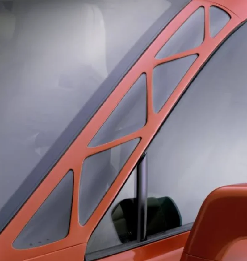
Automotive A pillar
Aerospace Industry
Tapered and joggled flanges are common on wing ribs where they deliver stiffness within critical weight limits.
HVAC
A duct joint uses flanges to join adjacent HVAC duct sections. A hem can also stiffen and cover the exposed sheet edge.
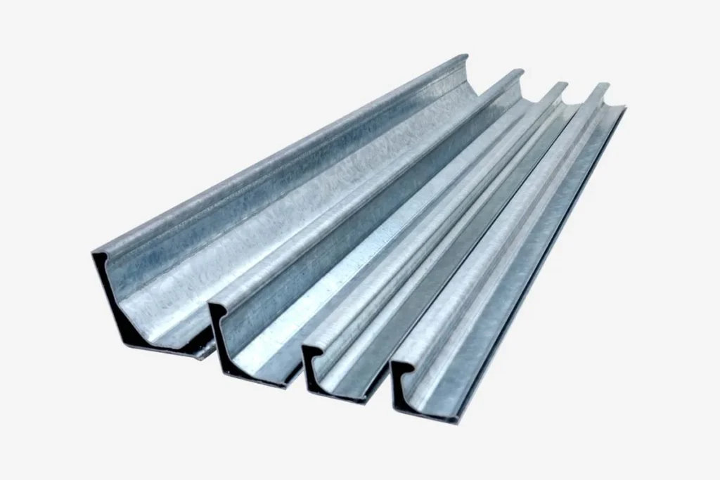
HVAC ductwork flanges
Electrical and Power Generation
Bent flanges stiffen a switchgear cabinet’s door frame and provide surfaces for mounting the adjoining panels.
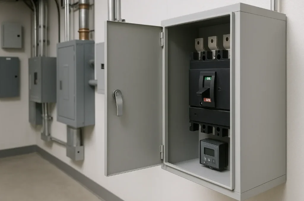
Electrical switchgear cabinet with flanges
Industrial Equipment and Process Plants
On a filter housing, a flange around the access opening provides a mounting surface for the cover.
Considerations for Choosing a Sheet Metal Flange for Your Application
Choose a sheet metal flange by aligning the part to these factors: Bend radius, flange length, the mating part, hole & fastener spacing, and the process.
Bend Radius
Choose an inside radius for the specific alloy, temper, and thickness. 6061-T6 aluminum generally needs a larger radius than more formable 5052 aluminum. See the sheet metal bend radius guide for material-specific starting values.
Flange Length
Start with about 4 times the sheet thickness when laying out the flange. Check the selected V-die chart for the actual minimum.
The Mating Part
Confirm fastener access, clearance, and overlap. Use a joggled flange when the overlap needs to sit flush.
Hole & Fastener Spacing
The goal is to prevent distortion of the hole. The standard distance is at least 2.5 times the thickness plus the bend radius from the bend line.
The Process
Stamping dies are for high volumes, while press brakes are for low to medium volumes.
Why a Custom Sheet Metal Flange Makes Sense
Specify a custom flange when a catalog part cannot meet the assembly’s hole pattern, flange length, or overlap requirements.
Common cases for this scenario are:
- A hole pattern or design not in the catalog
- An offset for a flush lap joint
- A flange longer than the usual length
Manufacturing Processes in Sheet Metal Flanging
The main manufacturing processes for sheet metal flanges are cutting, stamping, welding, and bending. The combination of these processes depends on the flange geometry, material, tolerance, and volume.
- Cutting: Cutting technologies include punching, laser cutting, and plasma cutting. They are used to produce blanks, bend reliefs, and holes.
- Stamping: Stamping dies are used to pierce and form the flange, typically in high-volume applications.
- Welding: This classic joining method comes in handy for joining bent strips and attaching the flange to other components. Popular welding technologies for this include TIG and spot welding.
- Bending: Bending entails folding the sheet metal along the bend line. It is a cost-effective process for low to medium volumes.
How to Produce a Sheet Metal Flange – the steps
The seven steps of forming a sheet metal flange are design, marking, cutting, clamping, bending, checking, and finishing.
Step 1: Design
Sheet metal flange design elements include length, radius, bend angle, and thickness. Others include material type and flange type. The bend allowance is also calculated.
Step 2: Marking
If a CNC machine is being used, the machinist or operator transfers the hole positions and bend lines to the CNC program. Otherwise, the details are transferred to the sheet.
Step 3: Cutting
The sheet metal blank is cut as designed, incorporating corner notches and bend reliefs.
Step 4: Clamping
The cut sheet is then positioned and secured on the machine. Align the bend lines with the tooling.
Step 5: Bending
Bending involves forming the flange according to the designed angles. Accommodate springback and use the right dies.
Step 6: Checking
Once the bending is complete, verify the hole positions, bend length, and bend angle. Common tools for this stage are protractors, gauges, and CMMs (Coordinate Measuring Machines).
Step 7: Finishing
The flange production process is not complete until the edges have been deburred and the component treated by passivation, coating, painting, or anodizing, as necessary.
Design Considerations and Specifications in Sheet Metal Flange
The key factors of sheet metal flange design are sheet metal bend radius, hole placement, tolerances, material thickness, and flange length.
- Bend Radius: Match bend radius to the material hardness. Harder materials require larger radii
- Hole Placement: The distance between holes and the bend line should be maintained at 2.5× thickness plus the bend radius
- Tolerances: Specify the applicable general tolerances on the drawing. Add individual tolerances for dimensions or angles critical to fit.
- Material Thickness: Specify the sheet thickness and alloy. Both affect feasible flange and hem lengths and the inside bend radius.
- Flange Length: Check the short leg against the tooling chart so the sheet remains supported on both die shoulders through the bend.
What is the Minimum Flange Distance?
For an initial layout, estimate the minimum flange length at about 4 times the sheet thickness.
At 4 times thickness, the starting estimates are 8 mm for 2 mm steel and 6 mm for 1.5 mm aluminum. Use the tooling chart’s measurement convention when dimensioning the flange.
The actual minimum depends on the V-opening, die shoulder radius, and bend geometry. The CONIC press brake guide [1] gives roughly 0.7 times the V-opening for a 90° V-die bend. Check the chart for the selected die to confirm that the short leg stays supported. A shorter flange may need dedicated tooling or another forming process.
Other important flange distances are hole-to-edge, bend relief, and hole-to-bend line.
| Feature | Recommended minimum |
| Flange length | About 4 times thickness for initial layout. Confirm with the die chart. |
| Hole to edge | 2 times thickness |
| Hole to bend line | 2.5 × thickness + bend radius |
| Bend relief width | ≥ material thickness |
| Hem length (open hem) | About 4 times thickness for the return. Confirm with the hemming tool. |
Use these as general guidelines. Exact values for a sheet metal flange depend on tooling, material, and manufacturer. Our sheet metal brackets guide is worth checking. It discusses flanges on mounts and supports.
Sheet Metal Flange Dimensions and Standards
ISO 2768:2026 replaced ISO 2768-1:1989 in November 2026. It specifies general tolerance limits for linear and angular sizes and excludes linear and angular distances. ISO 22081:2021 superseded the former geometrical tolerancing part, ISO 2768-2:1989.
For drawings that explicitly invoke ISO 2768-1:1989, use the class specified on the drawing. In class m (medium), a nominal linear dimension over 30 mm through 120 mm has a tolerance of ±0.3 mm. Exactly 30 mm falls in the previous band, at ±0.2 mm.
Legacy ISO 2768-1:1989 linear tolerances in mm [2]. External radii and chamfer heights use a separate table.
| Permissible deviations in mm for ranges in nominal lengths | f (fine) | Tolerance class designation (description) | v (very coarse) | |
| m (medium) | c (coarse) | |||
| 0.5 to 3 | ±0.05 | ±0.1 | ±0.2 | – |
| >3 to 6 | ±0.05 | ±0.1 | ±0.3 | ±0.5 |
| >6 to 30 | ±0.1 | ±0.2 | ±0.5 | ±1.0 |
| >30 to 120 | ±0.15 | ±0.3 | ±0.8 | ±1.5 |
| >120 to 400 | ±0.2 | ±0.5 | ±1.2 | ±2.5 |
| >400 to 1000 | ±0.3 | ±0.8 | ±2.0 | ±4.0 |
| >1000 to 2000 | ±0.5 | ±1.2 | ±3.0 | ±6.0 |
| >2000 to 4000 | – | ±2.0 | ±4.0 | ±8.0 |
ASME Y14.5: Defines GD&T for flange features such as face orientation and hole position.
DIN 6935: Covers cold bending of flat-rolled steel, including bend radii.
ISO 13920: Provides general tolerances for welded assemblies when a class is specified on the drawing.
Challenges in Sheet Metal Flanging
Flanging can be hindered by springback, cracking, and wrinkling. Each of these challenges can be controlled and managed through professional material selection, design, and tooling.
- Springback: The bend opens after the load is released, especially in higher-strength aluminum or stainless steel. Measure the springback on a trial bend, then overbend by the measured amount. Use a smaller radius only if the material and design allow it.
- Cracking: A tight bend can split the outer surface of hard brass or 6061-T6 aluminum. Use a larger inside radius, orient the bend line across the rolling direction where possible, or select a more formable alloy such as 5052 when the design permits.
- Wrinkling: A shrink flange puts the edge in compression, which can make it ripple. Where the design permits, shorten the flange or add relief cuts. A pressure pad can help control the sheet during forming.
Select the bend radius and tooling together to balance springback and cracking. Our sheet metal bend radius guide outlines the values for different materials.
Conclusion
A sheet metal flange stiffens the part or provides a joining surface. A hem folds the exposed edge back when the part needs a covered edge.
Whether joggled, hemmed, straight, or contoured, each flange type suits a specific application.
Experienced engineers match the flange type to material, specified geometry, and the design guidelines. For rules covering flanges and more, check our sheet metal design guide.
ProleanMFG’s sheet metal bending services list a standard bend-angle tolerance of ±1°. A high-precision setup may reach ±0.5°, depending on the material and bend geometry. Confirm any tighter tolerance during drawing review.
Upload your CAD design, and our expert will respond with a quote within 24 hours. Contact us today!
FAQs
What is a flange in sheet metal?
A flange is a bent edge that adds stiffness or gives another part a surface to attach to. A hem is a flange whose edge folds back toward the sheet.
What is a metal flange used for?
Sheet metal flanges stiffen panels and provide joining surfaces. Examples include duct joints, enclosure doors, and structural panels.
What is the minimum flange distance?
Use about 4 times the sheet thickness as a starting estimate. The actual minimum depends on the V-die opening and shoulder geometry, so confirm it with the selected tool’s chart.
What are the types of flanges?
Common types of flanges include straight, stretch, shrink, joggled, and hemmed flanges. Stretch and shrink flanges follow curved bend lines. A joggle creates an offset for an overlap.
Resources
[1] CONIC, Press Brake Technical Guide, Vol. 3: Minimum Flange Length. See also WILA’s short-flange tooling guide.
[2] ISO 2768-1:1989, legacy standard and Table 1. Current edition: ISO 2768:2026.