Sheet metal bending is a manufacturing process that deforms metal sheets into specific angular shapes, usually through an external force, typically using a press brake or rolling machine. Sheet metal bending can help you produce lighter and stronger sheet metal parts with fewer components. From enclosures to cabinet parts and automotive structures, choosing the right bending parameters can directly reduce material usage and rework.
This detailed guide provides a systematic explanation of sheet metal bending types (V-bending, bottoming, coining, etc), calculations, and in-depth knowledge about K-factors and bend allowance. It also details key points for DFM in sheet metal.
What Is Sheet Metal Bending?
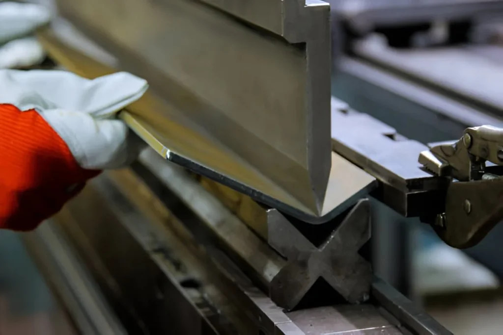
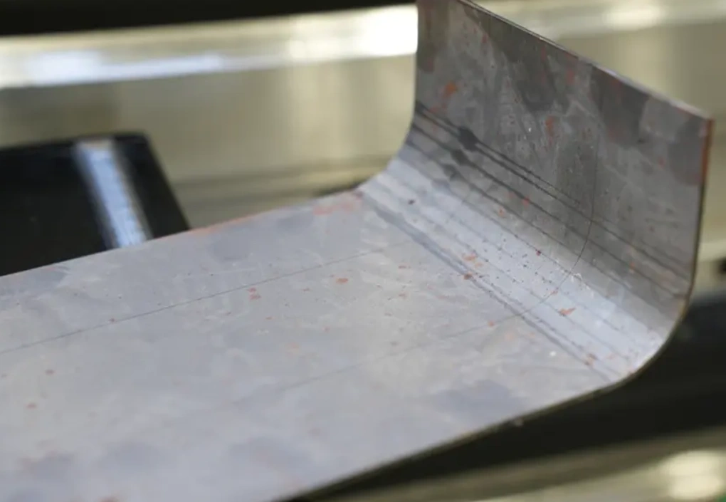
Sheet Metal Pleate Bending
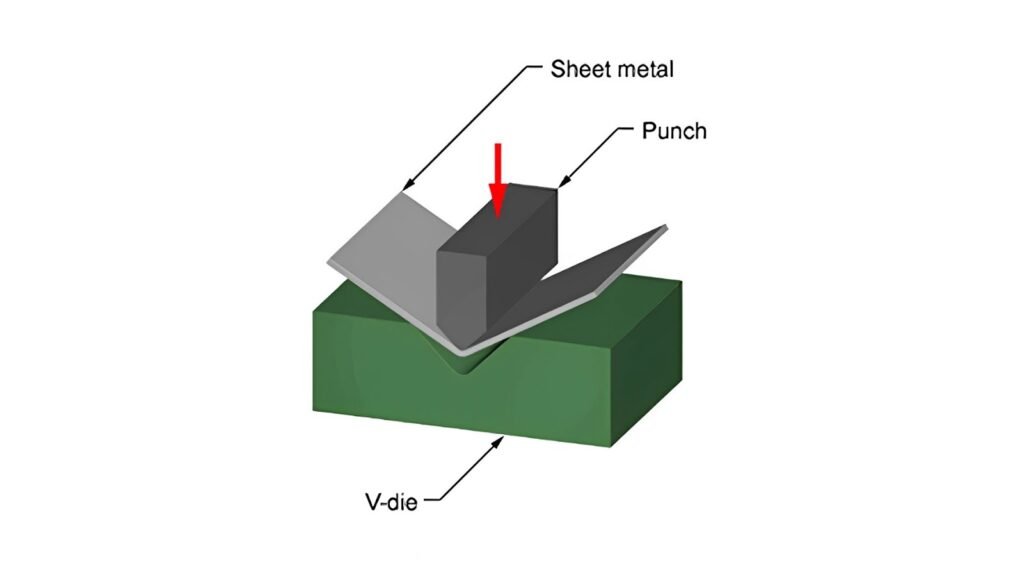
Sheet metal bending involves deforming a flat metal sheet into a desired shape using an external force beyond the material’s yield strength that results in a permanent deformation. Sheet metal bending is done in a press brake, where a punch forces the sheet into a V-shaped die, or using a rolling machine for any curved profiles.
Bending enhances structural integrity by increasing stiffness, redistributing stresses, and enabling large sheet metal geometries without the need for excessive tooling and custom machining.
Types of Sheet Metal Bends
Sheet metal bending uses various bend types, each suited for a particular application and geometry.
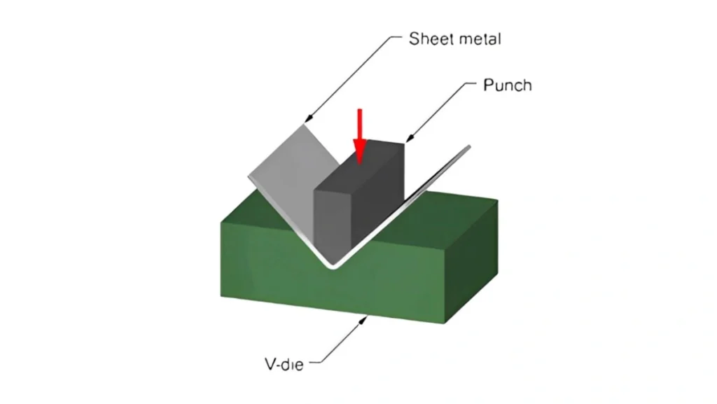
V-Bending
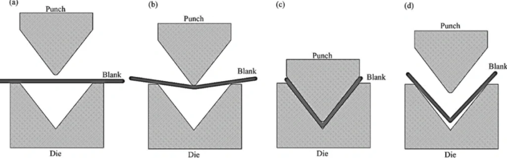
V bending process
The most common bending method for sheet metal is V-bending, which uses a punch and a V-shaped die on a press brake. It includes:
- Air bending: In this process, the sheet rests on two points on the V-di,e, and the punch bends it without fully contacting the die, leaving an “air gap”. This method allows multiple bend angles with a single die, but it is less precise because of springback.
- Bottoming: In this process, the punch presses the sheet fully into the V-die, matching the die’s angle. It offers higher precision and reduced springback but costs more due to specific dies for each angle.
- Coining: In coining, the punch penetrates the sheet, creating a precise bend with minimal springback. It requires significant force and specific tooling, but is rarely used because of advanced press brakes.
Roll Bending

Roll bending uses rollers to form cylindrical and conical shapes. A three-roll machine typically consists of two fixed bottom rolls and an adjustable top roll. Roll bending works by deforming the sheet as it passes through the rolls. Roll bending is commonly used for large radius bending or tube bending for cylindrical parts to ensure ends meet.
U-Bending
U bending Process
U-bending creates U-shaped profiles using a U-shaped punch and die. It is commonly used for channels and is similar to V bending but produces a symmetrical, U-shaped ccross-section
Rotary Bending
Rotary bending uses a rotating die to bend sheet metal, without scratching the surface.. It is suitable for sharp bends like 90°. Rotary bending can also produce U-channels with closely spaced flanges with minimal surface damage.
Edge Bending
Edge bending forms bends along the edge of the sheet using a die and punch. The die controls the inner radius and sheet positioning.
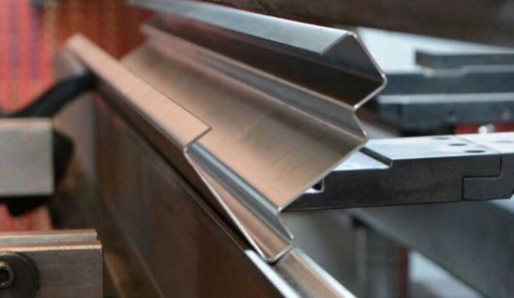
Channel Bending
Channel bending creates a C-shaped or channel profile using multiple bends. Channel bending is mostly used in architectural and structural components. Channel bending has a critical component called flange spacing, which can lead to interference during bending.
Hemming
Hemming involves folding the sheet edge back onto itself to create a rounded edge or to enhance strength. Hemming types include:
- Open Hem: Has a typical slight gap, with a minimum inside diameter equal to the material thickness and a return length of 4 times the thickness.
- Closed Hem: Fully closed or with no visible gaps, requires a minimum diameter equal to the material thickness and a return length 6 x the thickness.
- Teardrop Hem: Teardrop hem comes from its teardrop shape, balancing strength and flexibility, with similar dimensional requirements to open hems.
Sheet Metal Bending Methods
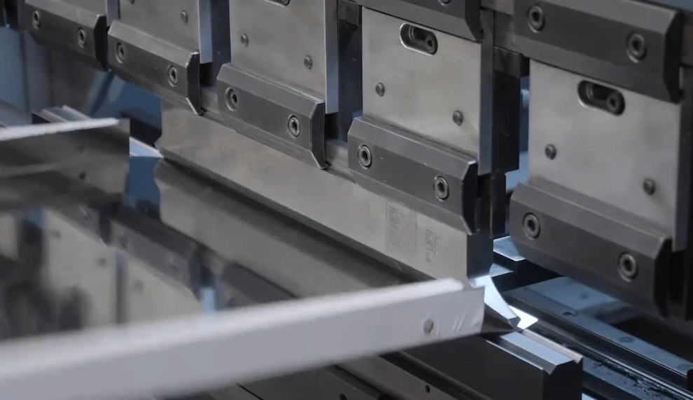
Brake Press
The brake press is the most common and main tool for sheet metal bending. Brake press uses a punch and a die to form precise bends. Brake presses come in different capabilities specified in tonnage. For example, force capacity of 500 tons or 800 tons, etc. It also has a width or maximum bend length of up to 7.2 meters.
Brake presses support air bending, bottoming, and coining, with air bending being the most common due to its flexibility and lower force requirements. Modern CNC brake presses enhance precision and reliability, often with tolerances of up to +/- 0.05 mm for high precision bending.
Rolling
Rolling uses a set of rollers to create curved and cylindrical shapes. Three-roll machines are standard, with configurations allowing for variable radii. Rolling can be used for materials from 1 mm to above 50 mm, depending on the machine’s tonnage, roll diameter and width. It is ideal for large radius bending and creating curves in sheet metal.
Common Bending Types and Machines Used
| Bending Type | Machine Used | Typical Applications | Precision Level |
|---|---|---|---|
| V-Bending | CNC Brake Press | Enclosures, brackets, panels | ±0.05–0.18 mm |
| Roll Bending | Three-Roll Machine | Pipes, cones, curved panels | ±0.5–1.0 mm |
| U-Bending | CNC Brake Press | Channels, structural frames | ±0.1–0.2 mm |
| Rotary Bending | Rotary Bender | Sharp bends, U-channels | ±0.1–0.15 mm |
| Edge Bending | Brake Press | Edge reinforcement | ±0.1–0.2 mm |
| Channel Bending | CNC Brake Press | Structural components | ±0.1–0.2 mm |
| Hemming | Brake Press | Edge finishing, part joining | ±0.1–0.2 mm |
Sheet Metal Bending Dimensions Guide
Designing for sheet metal bending requires dimensional guidelines to ensure manufacturability. These depend not only on the machine’s capability but also on the part structure. For example, sheet metal width, bending radius, and maximum bending angles.
Wall Thickness
Sheet metal parts should maintain uniform wall thickness, which is usually between 0.2 mm and 3 mm, depending on whether sheet or plate (>6mm) is being used. Consistent thickness reduces stress concentrations.
Material Thickness
The specific thickness of the sheet metal can affect the bending effectiveness. Thicker metal sheets require more force and a strategic approach
For instance, for mild steel, a general rule of thumb is 1 ton per meter per mm of thickness using a standard V-die. The specific tonnage requirements may vary based on bend radius, tooling, and machine setup.
Bend Parameters
The bend length and radius are important elements in sheet metal bending. The bend radius usually depends on the material and tooling. The bend length is guided by the part’s design requirements.
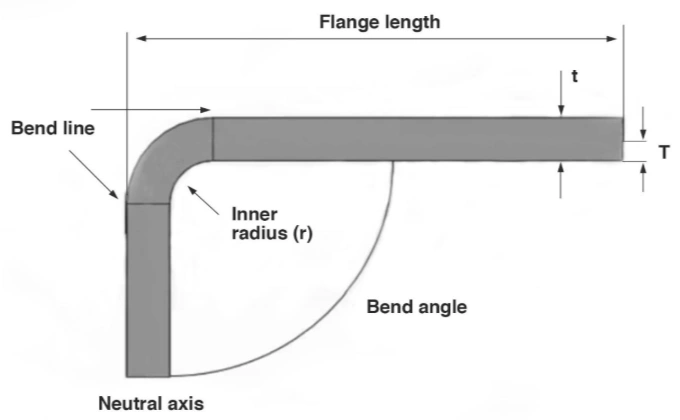
Bending parameters
Bend Radius
The minimum bend radius for sheet metal should be equal to or exceed the material thickness to prevent cracking. For instance, a 2 mm sheet requires its inner bend radius to be a minimum of 2 mm.
Inside vs. Outside Bend Radius
The inside bend radius (ir) is the curvature on the inner surface of the bend, while the outside radius is the sum of the inside radius and material thickness. Inner radius is critical for design calculations because it affects the bending and material stretching.
Bend Deduction
Bend deduction (BD) is the amount subtracted from the sum of the flat pattern lengths to account for material stretching during bending.
BD = 2 (r+T)tan(β/2) – BA
Minimum Flange Length
The minimum flange length depends on the die width and material thickness. For a 2 mm thick sheet with a 2 mm inside radius, the minimum flange length is approximately 8.5 mm.
Bend Relief
Bend reliefs are small cutouts at the bend line to prevent tearing or deformation. Typically, the relief width should be at least equal to the material thickness, and the length should exceed the sheet metal bend radius.
- Oblong Relief: Rounded ends reduce stress concentration
- Rectangular Relief: Simpler to cut
Bending Direction (Grain Direction Consideration)
Bending parallel to the material’s grain direction increases the risk of cracking, especially in aluminum bending. Perpendicular bending to the grain is preferred to ensure smooth surfaces and prevent fractures.
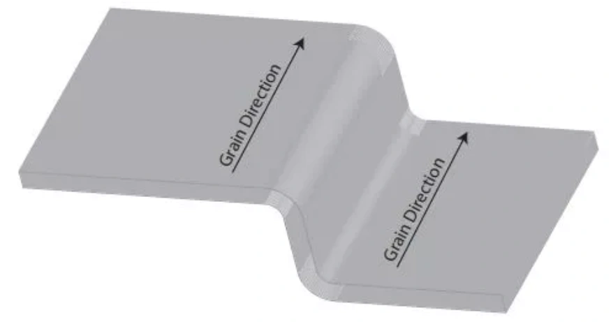
Bending and grain direction
Tolerances and Clearances
Tolerances depend on the bending method and material. CNC brake presses achieve standard tolerances of ±0.508 mm for forming and ±1° for angularity. High-precision setups can reach ±0.05 mm and ±0.5°.
Hole and Slot Proximity to Bends
Holes and slots near bends can deform due to material stretching. Recommended minimum distances are:
- Holes: 2.5T + ir from the bend face
- Slots: 4T + ir from the bend face
Hemming and Curling Considerations
- Curls: Require an outer radius of at least 2T and a minimum distance of the curl radius plus 6T from the bend.
- Hems: Open hems need a 4T return length, closed hems require a 6T return length, and teardrop hems require 4T with inside diameters equaling the material thickness.
Springback and Compensation
Springback occurs due to the material’s elasticity. It causes the material to revert to its original shape after bending.
- Higher tensile strength increases springback.
- Smaller bend radii reduce springback.
- Wider die openings increase springback.
Compensation involves overbending the material beyond the desired angle.
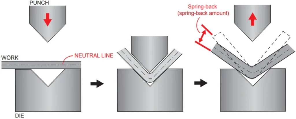
Springback effect
Minimum Hole Size and Distance from Edges
Holes should be at least 2T in diameter to avoid deformation. The minimum distance from a hole to the sheet edge is 2T to prevent bulging.
Most Common Sheet Metal Bending Techniques And K-Factor Tables
Air Bending
Air Bending Sheet Metal
Air bending is a popular bending method where the punch pushes the sheet into a V-shaped die without fully contacting the die bottom. The angle depends on how deep the punch penetrates, so it’s flexible.
- How it works: The sheet floats between the punch and die. Minimal contact means less force is required.
- Applications: Enclosures, cabinets, and non-critical structures.
- Advantages: Lower bending force, fewer tooling changes, adjustable angles.
- Limitations: Slightly lower precision and more springback than bottoming or coining.
Best for: Prototypes, medium-tolerance parts, and flexible production runs.
| Inside Radius Range (Relative to Thickness T) | Aluminum (Soft) | Aluminum (Medium) | Stainless Steel (Hard) |
|---|---|---|---|
| 0–1T | 0.33 | 0.36 | 0.40 |
| 1T–3T | 0.38 | 0.42 | 0.45 |
| >3T | 0.50 | 0.50 | 0.50 |
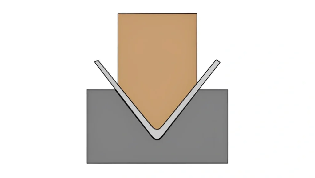
Bottom Bending (Bottoming)
Bottom Bending Sheet Metal
Bottom bending, or bottoming, forces the sheet to conform fully to the die shape. It results in greater angle accuracy and minimal springback.
- How it works: The punch drives the sheet into the die until the bottom touches it.
- Applications: Automotive panels, precision assemblies.
- Advantages: Better control over bend angles, reduced springback.
- Limitations: Requires dedicated tooling for each angle and material.
Best for: Tight-tolerance production and repetitive high-precision parts.
| Inside Radius Range (Relative to Thickness T) | Aluminum (Soft) | Aluminum (Medium) | Stainless Steel (Hard) |
|---|---|---|---|
| 0–1T | 0.38 | 0.40 | 0.43 |
| 1T–3T | 0.42 | 0.44 | 0.46 |
| >3T | 0.48 | 0.49 | 0.50 |
Coining
Sheet Metal Coining Process
Coining is a high-pressure bending method that compresses the sheet into the die, deforming the material past its yield point for permanent bending.
- How it works: The punch penetrates deeply, “coins” the bend into the sheet.
- Applications: Small electronic housings, aerospace components.
- Advantages: Near-zero springback, ultra-high precision.
- Limitations: High tool wear, higher tonnage requirements.
Best for: Thin sheets, precision parts, and critical design geometries.
| Inside Radius Range (Relative to Thickness T) | Aluminum (Soft) | Aluminum (Medium) | Stainless Steel (Hard) |
|---|---|---|---|
| 0–1T | 0.30 | 0.33 | 0.36 |
| 1T–3T | 0.35 | 0.38 | 0.41 |
| >3T | 0.42 | 0.44 | 0.46 |
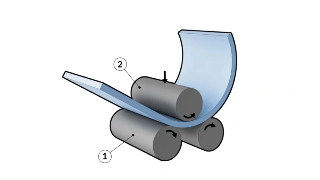
Roll Bending
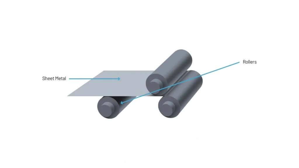
Sheet Metal Roll Bending
Roll bending makes large radius bends or cylindrical shapes by passing sheet metal through three rollers.
- How it works: Sheet metal is guided between three rollers (two adjustable, one fixed) to form curves.
- Applications: Pipes, tanks, ducts.
- Pros: Continuous curves, suitable for long parts.
- Cons: Not suitable for tight radii or short parts.
For: Circular components in HVAC, energy, or transport systems.
| Bend Radius Range | Aluminum (Soft) | Aluminum (Medium) | Stainless Steel (Hard) |
|---|---|---|---|
| 3T–5T | 0.45 | 0.46 | 0.47 |
| 5T–10T | 0.48 | 0.49 | 0.49 |
| >10T | 0.50 | 0.50 | 0.50 |
Wipe Bending
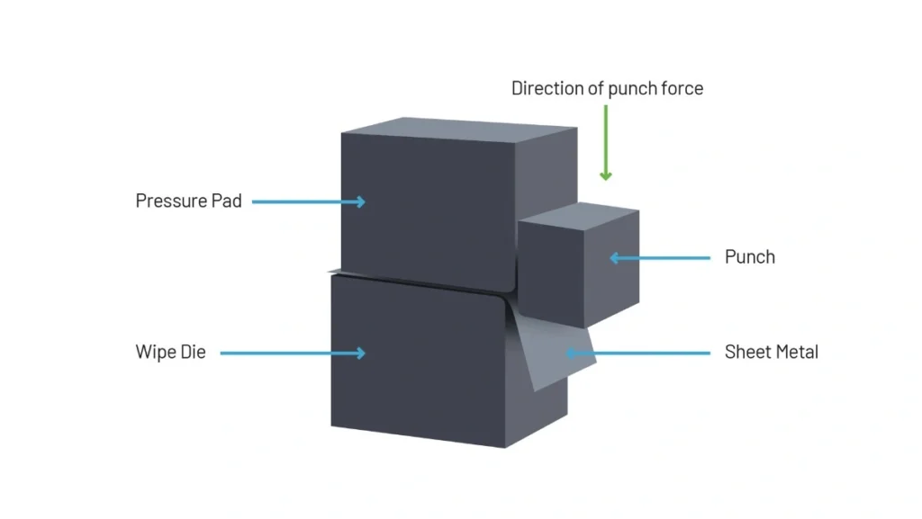
Wipe Bending Sheet Metal
Alt text: Diagram of sheet metal wipe bending process.
Wipe bending uses a wiping die that presses the sheet metal edge over a straight edge to form a 90° flange or similar profile.
- How it works: The sheet is clamped, and the edge is bent around a post with a wiping punch.
- Applications: Brackets, casings, and hardware.
- Pros: Fast, repeatable, high-volume production.
- Cons: Limited bend angle flexibility.
For: Mass production of edge bends in consumer electronics and appliances.
| Inside Radius Range (Relative to Thickness T) | Aluminum (Soft) | Aluminum (Medium) | Stainless Steel (Hard) |
|---|---|---|---|
| 0–1T | 0.35 | 0.37 | 0.40 |
| 1T–3T | 0.40 | 0.42 | 0.44 |
| >3T | 0.47 | 0.48 | 0.49 |
Rotary Bending
Rotary Bending Sheet Metal
Rotary bending uses a rotating die that rolls over the sheet to form a clean bend without scratching the material.
- How it works: The Roller die rotates as it presses the sheet, with no friction.
- Applications: Parts need a clean finish, like decorative panels.
- Advantages: Scratch-free finish, less marking on coated sheets.
- Limitations: More complex tooling is less standard than V-bending.
Best for: Coated, decorative, or aluminum parts where surface integrity is critical.
| Inside Radius Range (Relative to Thickness T) | Aluminum (Soft) | Aluminum (Medium) | Stainless Steel (Hard) |
|---|---|---|---|
| 0–1T | 0.34 | 0.36 | 0.39 |
| 1T–3T | 0.39 | 0.41 | 0.43 |
| >3T | 0.47 | 0.48 | 0.49 |
Bend allowance formula
Bend allowance = 180β (Kt+r)
- BA = Bend Allowance (mm)
- β = Bend Angle (°)
- ir = Inside Radius (mm)
- K = K-Factor
- T = Material Thickness (mm)
What Materials Are Suitable for Sheet Metal Bending?
The most suitable materials for CNC sheet metal bending are aluminum, stainless steel, mild steel, brass, and copper. Titanium can also work for the thinner sheets. These materials create reliable fabricated items because they are ductile and formable, meaning they can withstand significant deformation without damage or cracking.
Each of the metals has specific properties, which are outlined next.
Aluminum
Aluminum CNC bending
Aluminum is a perfect choice for bent sheet parts where corrosion resistance, strength, and low weight are crucial. Coupling these properties with high malleability qualifies the material for critical applications like automotive and aerospace.
Steel
Steel sheet bending
The strength and dynamism of steel in different operating environments make it a common material in CNC sheet metal bending. The options under this category include mild steel for general-purpose jobs, alloy steel for demanding environments, and high-strength steel for structural applications.
Stainless Steel
Stainless steel is also corrosion-resistant, but it combines this with high aesthetic appeal and strength. The chemical and marine industries prefer this material for their sheet metal bending processes.
Copper
Copper is very malleable, hence suitable for CNC bending projects. Parts made from this material provide excellent electrical and thermal conductivity, alongside the highly notable corrosion resistance.
Copper may be initially soft when bending, but it can harden and perform excellently in work conditions. Annealing takes care of sections of the material that are difficult to bend.
Titanium
Titanium is stiff and strong, so it can easily spring back after being bent. Yet, the material’s fatigue resistance, corrosion resistance, biocompatibility, and high strength-to-weight ratio are too good to ignore.
Manufacturers use bending techniques such as laser bending and hot forming to produce the much-needed titanium parts.
Important material parameters are sheet thickness, metal gauge, and grain direction. Thicker metals require more force and larger bend radii.
Advantages of Sheet Metal Bending
Sheet metal bending has many advantages for your projects.
- Speed of manufacturing: CNC bending enables rapid production, with setups completed in under an hour for low to medium volumes.
- High Accuracy: Modern CNC presses achieve tolerances as tight as ±0.05 mm.
- Reduced Post-Processing: Bending typically requires no additional finishing, unlike welding.
- Lightweight Parts: Bending adds stiffness without increasing material use.
- Low Cost and Minimal Tooling: Standard tooling eliminates the need for custom dies, reducing costs and lead times.
- Simplified Assembly: Single-piece designs reduce the need for welding or fasteners
Limitations of Sheet Metal Bending
- Thickness Limitations: Thicker materials (>20 mm) require higher tonnage and result in larger bend radii or cracking.
- Consistent Thickness Requirement: Parts must maintain uniform thickness for optimal results
- Production Volume: Bending is less cost-effective for high volumes (>10,000 units), where stamping is preferred.
- Potential for Defects: Bending can cause surface scratches, indentations, or feature distortion if not designed properly.
- Tooling Constraints: Close bends or complex geometries require specialized tooling
Sheet Metal Achievable Tolerance Guide
| Feature | Standard Tolerance | High-Precision Tolerance |
|---|---|---|
| Forming/Bending | ±0.508 mm (0.020″) | ±0.05 mm (0.002″) |
| Bend Angle | ±1° | ±0.5° |
| Bend to Hole/Feature | ±0.254 mm (0.010″) | ±0.05 mm (0.002″) |
| Bend to Edge | ±0.254 mm (0.010″) | ±0.05 mm (0.002″) |
| Bend to Bend | ±0.381 mm (0.015″) | ±0.1 mm (0.004″) |
| Hole to Hole | ±0.127 mm (0.005″) | ±0.05 mm (0.002″) |
| Edge to Hole | ±0.127 mm (0.005″) | ±0.05 mm (0.002″) |
Methods for Sheet Metal Cutting
Sheet metal bending is paired with cutting processes to prepare flat patterns for bending. Common cutting methods include:
- Laser Cutting: Offers high precision (±0.1 mm) for complex geometries. It is suitable for thicknesses from 0.5 mm to 20 mm. No custom tooling is required.
- CNC Punching: Ideal for parts with multiple holes or embossing (±0.12 mm tolerances). Limited to thicknesses up to 4 mm without special tooling
- Shearing: Used for simple, straight cuts with low tolerances (±0.5 mm), suitable for thin materials (0.5–4 mm).
- Plasma Cutting: Suitable for thicker materials (up to 50 mm) but less precise (±0.5 – 1 mm) and creates heat-affected zones that affect bending.
| Process | Precision | Thickness (mm) | Custom Tooling | Lead Time |
|---|---|---|---|---|
| Laser Cutting | +/- 0.10 mm | 0.5-20 | No | < 72 hours |
| CNC Punching | +/- 0.12 mm | 0.5-4 | Sometimes | < 72 hours |
| Shearing | +/- 0.50 mm | 0.5-4 | No | < 72 hours |
| Plasma Cutting | +/- 0.5-1 mm | 0.5-50 | No | < 72 hours |
Conclusion
Sheet metal bending is an efficient manufacturing process that can create lightweight, strong, and durable components from boxes to automotive panels. By using design guidelines for sheet metal bending, like uniform wall thickness considerations and radii, you can ensure the long-term manufacturability and cost effectiveness for medium volume production.