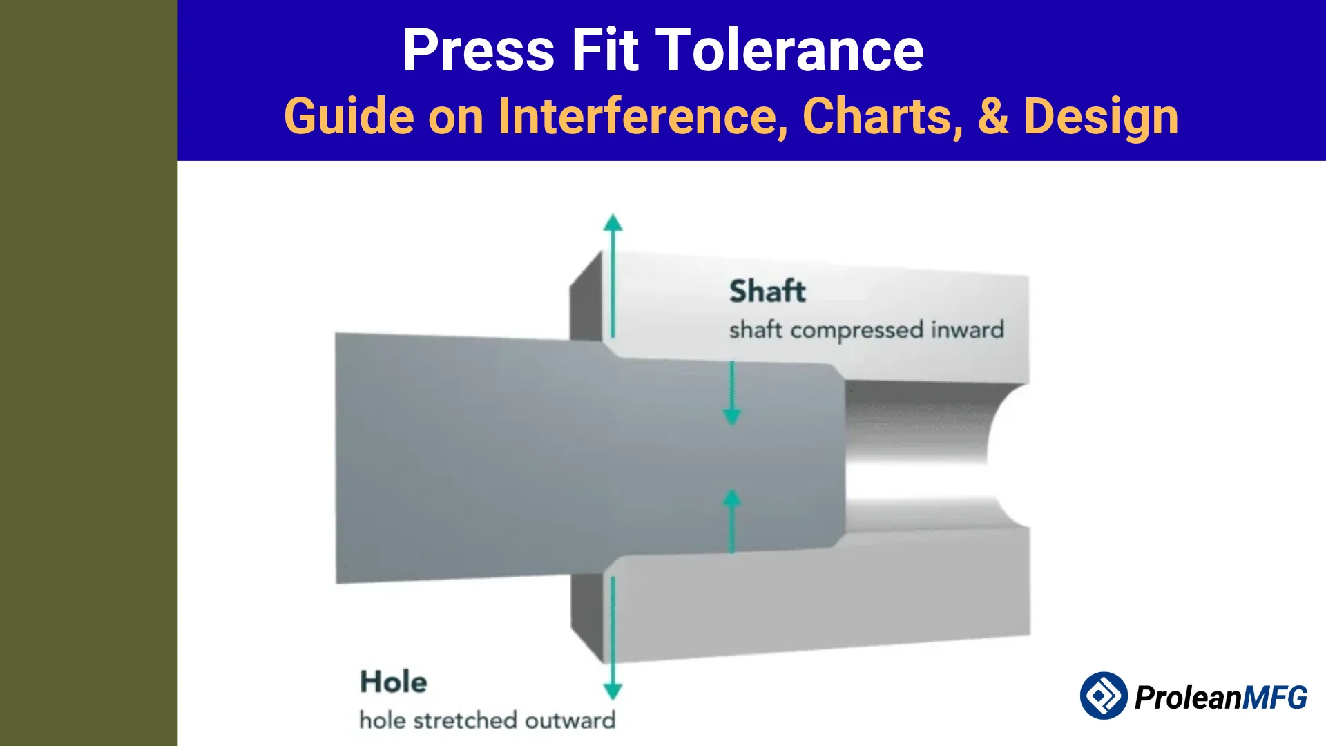
A few micrometers determine whether a press fit fails immediately when a load is applied or holds for the designed life. Press fit tolerance is the permissible size range for mating parts, often a shaft and bore. This range must be held within the CNC machining tolerances that the process can dependably deliver.
For a 25 mm shaft, H7/p6 gives about 0.001 to 0.035 mm of interference and H7/s6 about 0.014 to 0.048 mm. Bushings, gears, and spindles all follow these tolerance limits.
When executed right, a press fit tolerance provides a dependable high-strength joint for cost-effective assemblies. The joint doesn’t require adhesives, fasteners, or keys. Such a joint prevents loosening and expensive rework.
Read this guide for how to check press fit tolerance charts, calculate interference, and avoid press fit errors. This knowledge will help you specify press fits that can be manufactured and verified.
Key Takeaways
- Interference is the shaft size minus the hole size. For Ø25 H7/p6, the interference ranges from 0.001 to 0.035 mm.
- A press fit tolerance ensures that the shaft size is always larger than the bore.
- H7/s6 aligns with strong interference or permanent torque transfer. H7/p6 is for light interference.
- H7/u6 or heavy interference requires a shrink fit to prevent pressing-related galling.
What Are Fits?
An engineering fit is how two mating features relate dimensionally. This description mostly applies to holes and shafts. The three main types of fits are clearance, interference, and transition fits.
These fits can be further categorized as shown in the diagram below.
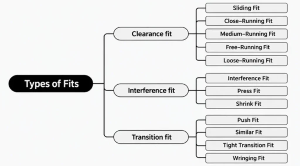
Categories of fits in mechanical engineering
What Is A Press Fit?
A press fit is an interference fit. Interference fits are defined by the smallest possible shaft being larger than the largest possible hole. During assembly involving an interference fit, a temporary temperature difference or mechanical force is applied.
For the press fit sub-category, the two parts are assembled using mechanical force. Both parts are at room temperature. But for shrink fit, a temporary temperature difference is applied between the mating parts.
Press Fit vs Clearance Fit and Transition Fit
A press fit creates a high-friction joint, while clearance and transition fits support easy assembly and relative movement. So, choosing between the fits depends on whether the joint is for free movement or load transmission.
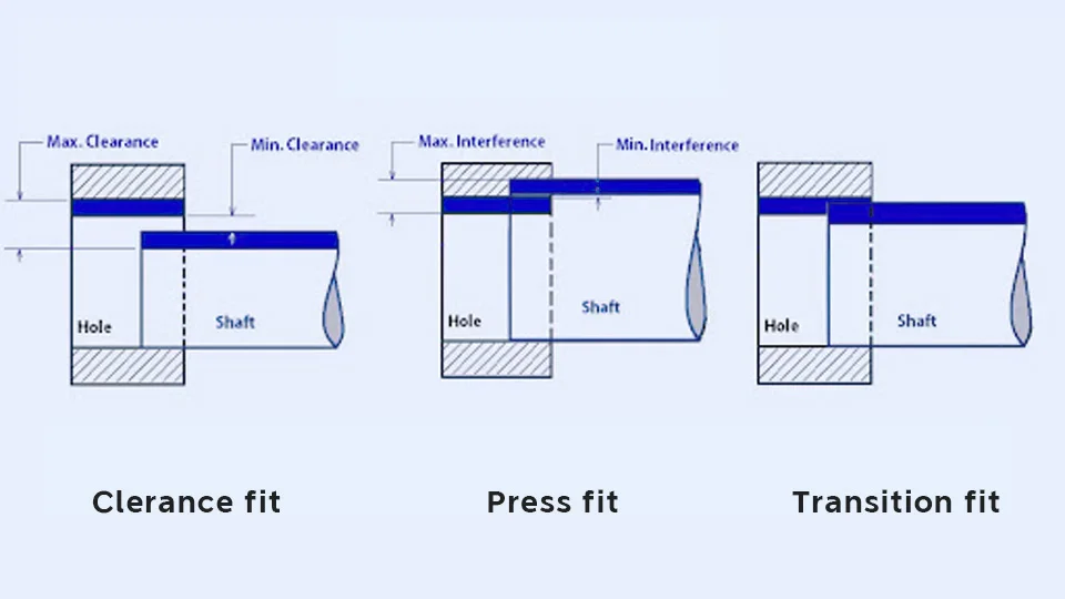
Types of fit
Factors Affecting Press Fit
A press fit’s performance depends on surface roughness, interference, material properties, assembly method, manufacturing tolerance, and temperature. Adjust any of these factors, and you will change the joint’s stress and holding force.
Surface Roughness: The designed interference is easier to maintain on a smooth surface than on a rough one. A rough surface flattens during assembly, leading to a loose joint.
Interference: The interference should create a good balance between the assembly force and holding force. Higher interference increases the holding force, but also increases the assembly force.
Material Properties: The deformation of a part depends on the material’s hardness, modulus of elasticity, and yield strength. Aluminum is one of the materials that can gall during assembly.
Assembly Method: A consistent joint results from slow, measured pressing. The opposite is rushed assembly, which can damage the mating surfaces and produce a loose joint.
Manufacturing Tolerance: The nominal value on the drawing is bound to differ from the manufacturing tolerance, which is the permissible size variation limit in production for the hub and shaft to work properly.
Note that the specific tightness will vary from one assembly to another. The joint may be more predictable with tighter tolerances, but this translates to higher machining and inspection costs.
Consider this example of a 20 mm H7/s6 press fit:
- Shaft: 20.035 to 20.048 mm (+35 to +48 µm)
- Hub Hole: 20.000 to 20.021 mm (+0 to +21 µm)
The tightest possible fit produces a 48 µm material overlap. The loosest possible fit produces a 14 µm overlap. There is a 34 µm variance in tightness between assemblies. This affects the final holding force.
Temperature: The thermal performance of the mating materials can either overstress or loosen the joint. It depends on the temperature variation.
If the shaft and hub materials are different, the interference varies with temperature because of the different expansion rates. The joint can overstress from cooling or loosen from heating depending on the relative expansion of the parts.
Example:
Consider aluminum, whose expansion rate is approximately twice that of steel (23 µm/m°C vs. 11 to 12 µm/m°C).
In a steel shaft/aluminum hub or housing assembly, the aluminum hole expands much faster than the steel shaft as the assembly heats up. The interference reduces due to different expansion rates. The joint can loosen or fail as the operating temperature rises.
How to Calculate Tolerance Press Fit
The basic formula for press fit interference is;
Interference = Diameter of Shaft − Diameter of Hole
Minimum interference = smallest shaft − largest hole
Maximum interference = largest shaft − smallest hole
Interference relates to the Lamé-based relation for thick-walled cylinders to determine the contact pressure P.
P = (δ / D) × [E_shaft × E_housing / (E_shaft + E_housing)]
Where,
δ = diametral interference
D = nominal diameter
E = Young’s modulus
The relationship is even simpler for a steel-on-steel assembly.
F = μ × P × π × D × L
Where,
μ = coefficient of friction
L = contact length
Worked example:
This is for Ø25 H7/p6 illustration
Hole: 25.000 to 25.022 mm. Shaft: 25.023 to 25.035 mm.
Minimum interference = 25.022 − 25.022 = 0.001 mm
Maximum interference = 25.035 − 25.000 = 0.035 mm
Press Fit Tolerance Charts
The charts below use tolerance press fit codes to generate interference numbers applicable in a drawing. They comprise an ISO table comparing p6 to u6 at Ø25 mm, an H7/p6 chart by nominal size from 6 to 120 mm, and an ANSI B4.1 inch table for FN 1 to FN 4.
IT7, IT6, and other tolerance grades follow ISO 286.
ISO Press Fit Tolerance Table (Ø25 mm, Hole Basis)
The hole is H7 throughout, ranging from 25.000 to 25.021 mm. Only the shaft class changes.
Table for ISO Press Fit Tolerance (Ø25 mm, Hole Basis)
| Fit | Shaft limits (mm) | Min interference (µm) | Max interference(µm) | Typical use |
| H7/p6 | 25.022 to 25.035 | 1 | 35 | Bearing seats, location |
| H7/r6 | 25.028 to 25.041 | 7 | 41 | Medium-duty press fits |
| H7/s6 | 25.035 to 25.048 | 14 | 48 | Torque transfer (permanent) |
| H7/t6 | 25.041 to 25.054 | 20 | 54 | Heavy-duty joints |
| H7/u6 | 25.048 to 25.061 | 27 | 61 | Shrink fits, heavy-duty joints |
H7/p6 Press Fit Chart by Nominal Size
The chart below shows the H7/p6 limits and the respective minimum and maximum interference for nominal sizes from 3 to 120 mm.
A chart of H7/p6 Press Fit by Nominal Size
| Nominal size (mm) | H7 hole (µm) | p6 shaft (µm) | Min interference (µm) | Max interference (µm) |
| Over 3 to 6 | 0 to +12 | +12 to +20 | 0 | 20 |
| Over 6 to 10 | 0 to +15 | +15 to +24 | 0 | 24 |
| Over 10 to 18 | 0 to +18 | +18 to +29 | 0 | 29 |
| Over 18 to 30 | 0 to +21 | +22 to +35 | 1 | 35 |
| Over 30 to 50 | 0 to +25 | +26 to +42 | 1 | 42 |
| Over 50 to 80 | 0 to +30 | +32 to +51 | 2 | 51 |
| Over 80 to 120 | 0 to +35 | +37 to +59 | 2 | 59 |
[2]
Inch Press Fit Tolerance Table (ANSI B4.1 Force and Shrink Fits)
Many US drawings replace ISO codes with ANSI B4.1 classes. Consider the following maximum and minimum interference values in thousandths of an inch (0.001 in).
Table of maximum and minimum interference values in thousandths of an inch (0.001 in)
| Nominal size (in) | FN 1 Light drive | FN 2 Medium drive | FN 3 Heavy drive | FN 4 Force fit |
| 0.95 to 1.19 | 0.3 to 1.2 | 0.6 to 1.9 | 0.8 to 2.1 | 1.0 to 2.3 |
| 1.97 to 2.56 | 0.6 to 1.8 | 0.8 to 2.7 | 1.3 to 3.2 | 2.3 to 4.2 |
| 3.94 to 4.73 | 1.1 to 2.6 | 1.6 to 3.9 | 2.6 to 4.9 | 4.6 to 6.9 |
| 7.09 to 7.88 | 1.8 to 3.8 | 3.2 to 6.2 | 5.2 to 8.2 | 7.2 to 10.2 |
[3]
How to Choose a Press Fit Tolerance
The factors to work through for a suitable press fit tolerance are holding force
stress limits, material, operating temperature, assembly method, and required fit strength.
Holding Force
Start with the force the joint must carry. List the loads, including cyclic loading, axial push-out force, and transmitted torque. Define the joint holding mechanism or capacity, specifically in terms of friction coefficient, contact area, and contact pressure.
The formula for the axial holding force is;
F = μ × p × π × D × L,
where
μ is the friction coefficient
p is the contact pressure
D is the nominal diameter
L is the engagement length
Determine the Stress Limits
The stress in both the bore and shaft is below yield. For the shaft, check for compressive stress, which should be uniform across the shaft length.
For the bore, tensile stress peaks at the bore surface.
Material
To account for the material, determine its strength and stiffness, which affect how the interference converts into deformation or contact pressure. The wall thickness of the mating component also matters: a thicker section expands less and carries more pressure than a thinner one.
Operating Temperature
Consider the working temperature range when determining the thermal influence on interference. The rate of size change depends on the material type.
- If the hub expands more than the shaft, interference reduces. This can loosen the joint.
- If the shaft expands more than the hub, interference increases. Stress can surpass the limit.
Assembly Method
Use press fit assembly only when the interference size allows. This fit suits medium or light interference. It also works well if the mating parts can be lubricated and aligned.
Otherwise, if the interference is heavy, you may need to use shrink fit to prevent galling and part damage.
Required Fit Strength
Match the class to joint application.
- H7/p6 – location and bearing seats
- H7/s6 – permanent torque transfer
- H7/u6 – heavy duty joints
It is always recommended to perform a press-in force check before settling on a class. From experience, the safety factor for holding force for permanent joints should be between 1.5 and 2.5.
Upload your CAD drawing today so the CNC machining team can specify the press fit tolerance for you after analyses, including CNC machining tolerance vs cost comparison.
Effect of Press Fit Tolerance on CNC Machining
Tolerance press fit sets the CNC machining accuracy and surface finish requirements. The ProleanMFG team observes the limits as follows:
Dimensional accuracy: Fine boring or reaming holds an H7 bore (IT7). The shaft can be CNC machined to IT6. Since the size difference between the shaft and bore is critical, machining both is necessary for the maintenance of the interference based on the drawing.
Surface Finish: The surface finish for both the shaft and bore is typically within Ra 0.8 to 1.6 µm. The finish has to be well controlled to avoid loss of interference as peaks on rougher surfaces flatten.
Lead-in Chamfers: It is necessary to add a lead-in chamfer of around 15° to help in self-centering.
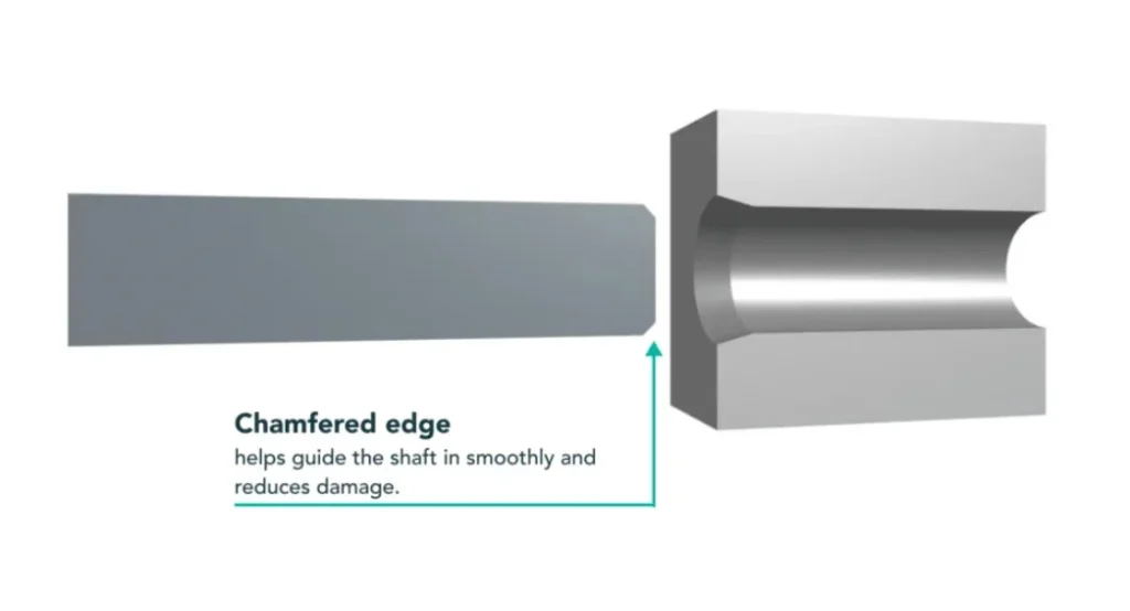
Lead-in chamfer
Geometric Form: Cylindricity and roundness are commonly approximately half the tolerance size – 0.006 mm for a Ø25 IT6 shaft
Inspection: A CMM and air gauge are some instruments used to check the bore. This step ensures the shaft and bore match the drawing specifications.
Common Press Fit Tolerance Challenges and Solutions
The most common tolerance press fit challenges are Joint slip, excessive assembly force, fretting corrosion, surface damage, and joint loosening at operating temperature.
Most of these can be traced back to either poor surface condition or the wrong interference. The good thing is that there is a solution to each of these challenges.
| Press fit tolerance challenge | Cause | Solution |
| Joint slip | Smooth surface or too little interference | Adjust the surface finish or increase the interference |
| Excessive Assembly Force | Misalignment, too much interference | Use lead-in chamfersReduce the interference Use shrink fit instead |
| Fretting Corrosion | Micro-movement of the mating parts under cyclic loading | CoatingUsing compatible materials for bore and shaftIncrease the interference |
| Surface Damage | Pressing-related scoring or galling | Proper alignment of the mating partsLubrication Slow pressing |
| Joint loosening at operating temperature | Materials’ thermal expansion differences | Consider highest operating temperature for designMatch the materials |
With the causes and solutions of press fit challenges now clear, the challenge now is to apply the fixes early. The specified tolerance should be deliverable by the CNC machining process and joint.
Conclusion
Press fit performance is only as good as the design. A professional press-fit tolerance balances stress against holding force.
Match the class to duty: H7/u6 for shrink fit, H7/s6 for permanent torque, and H7/p6 for location and bearing seats.
Derive the interference window from the limits: Maximum is largest shaft minus smallest bore, while minimum is smallest shaft minus largest bore.
Are you wondering what press fit tolerance to use for your application? Our CNC machining services specialists can specify the right tolerances and hold the right fit. Upload your CAD design today, and we will respond with recommendations and a no-obligation quote within 24 hours.
Resources
[1]https://www.iso.org/standard/45975.html