A single misinterpreted reference point can render a batch useless, even when the CNC machining tolerances match the dimensions. The reference in this context is the datum in geometric dimensioning and tolerancing (GD&T).
A datum in a drawing supports callouts and determines the fixturing, machining, and inspection processes. With the right datum, the assembly fits are predictable, rework costs are lower, and inspection-related disputes are fewer.
As you specify your datums, this article’s coverage of datum definition, datum types, datum establishment process, and the 3-2-1 locating principle will be helpful.
Key Takeaways
- Datums are theoretical reference points, axes, or planes
- The 3-2-1 principle guides fixture locating and constrains six degrees of freedom.
- For fewer setups, simpler fixturing, and lower cost, datums should be chosen for accessibility and function
First, the GD&T Definition
A good starting point is the GD&T definition. Geometric Dimensioning and Tolerancing (GD&T) is a system of rules and symbols for standard tolerance specification, set out in the ASME Y14.5 standard. [1] The system communicates a machined part’s variation for functionality.
GD&T principles and symbols matter in CNC machining because they simplify and minimize interpretation. They ensure clarity between design and manufacturing steps.
Compared to conventional tolerancing that focuses on allowable size deviations for the machined part, GD&T is more detailed. The system clarifies the allowable variation in a part’s form, location, runout, orientation, and profile.
Form – Circularity, flatness, or straightness
Location – Position
Runout – Rotational deviations
Orientation – Angularity, parallelism, and perpendicularity
Profile – Complex surfaces
Put frankly, GD&T optimizes economy and precision in CNC machining.
What is a Datum in GD&T?
In CNC machining, a datum is a theoretically ideal geometric reference plane, point, or line. It establishes a standard reference frame for a part’s location, orientation, runout, and profile.
A GD&T datum is a theoretically exact plane, axis, or point, which is established from a physical datum feature on the part. In other words, key surfaces in a component are designated as datum features.
A datum is different from actual surfaces because it doesn’t contain form deviations. A comparison between an actual plane and a datum is shown in the diagram below.
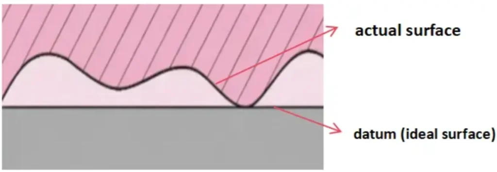
Datum vs. actual surface
Types of Datum: Datum Features, Datums, and Datum Reference Frames
Four related terms separate the real part from the theoretical reference, namely, the datum feature, datum feature simulator, datum, and datum reference frame (DRF).
- Datum feature
- Datum feature simulator
- Datum
- Datum reference frame (DRF)
Types of Datum By Datum Feature
The three categories of datum by datum feature are planar, cylindrical, and spherical.
Planar feature: Provides a datum plane.
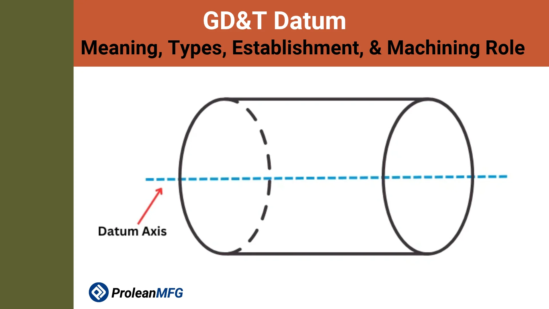
Cylindrical feature: Provides a datum axis.
Spherical feature: Provides a datum center point.
Each datum feature on a datum drawing is identified with a symbol datum. This entails a letter in a frame, which points to the feature with a triangle.
What is a Datum Feature?
A datum feature is a specific feature on a manufactured part, such as an edge or face, used to reference the establishment of a datum for manufacturing, inspection, or measurement.
What is a Datum Feature Simulator?
A datum feature simulator is a theoretically flawless counterpart of the datum feature. Manufacturers or inspectors use the datum feature simulator to establish the datum.
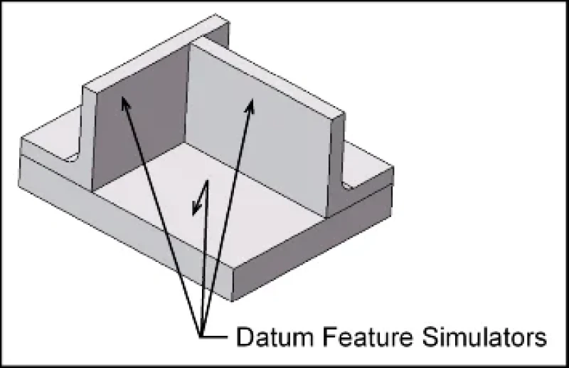
Datum feature simulators
The concept of the datum feature and datum feature simulator is captured in the table below.
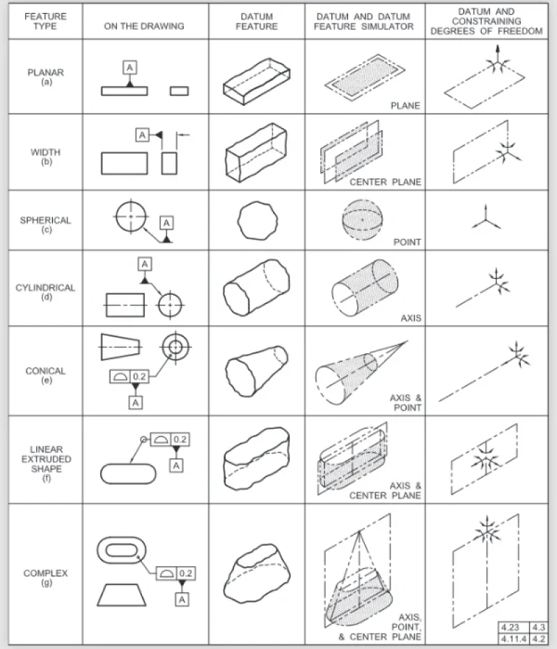
Datum, datum feature, and datum feature simulator
Datum System (Datum Reference Plane)
A datum reference frame (DRF) or datum system is a set of three planes perpendicular to each other. The planes are generated from the interaction between primary, secondary, and tertiary datums.
A full A-B-C DRF locks all six degrees of freedom, which comprise 3 translational (X, Y, Z movement) and 3 rotational (pitch, roll, yaw).
How is Datum Calculated?
There is no general formula for establishing a datum. A theoretically exact simulator is used to establish a datum from the physical datum feature, following the requirements of ISO 5459:2024 for datums and datum systems. [2]
Different datum simulations can give different measurements on the same part. Results are consistent when the simulation method specified on the drawing is followed.
The main ways to use a simulator are;
- CMM software – Probed points are used to find the perfect point, axis, or plane.
- Physical simulation – The simulator is a fixture, gauge, or surface plate. It is used to contact the part.
- High-Point Contact – The highest points of the feature are used to support the part.
Datum Designation on a Drawing
The designer designates datum on a drawing using the following steps:
Step 1: Select the datum feature
Step 2: Label the datum feature with the datum feature symbol
Step 3: Rank the datum feature (primary, secondary, tertiary)
Step 4: Reference the datum feature in the feature control frame
What is the 3 2 1 Rule for Datum?
The 3-2-1 principle is a common workholding method that constrains the six degrees of freedom using six locating contacts.
The six degrees comprise three for translations (X, Y, Z) and three for rotations (pitch, roll, yaw).
Here’s how each group constrains the part:
- Primary (3 contacts): Restricts one translation and two rotations
- Secondary (2 contacts): Restricts one translation and one rotation
- Tertiary (1 contact): Restricts the remaining translation
One instance where the principle comes into focus is when mounting workpieces in CNC fixtures for machining. The two goals are to accurately position the part and restrict its movement by restraining the six degrees of freedom.
The 3-2-1 principle can also be referred to as the six-point method because it involves six fixed points.
As a fixture-locating method, 3-2-1 usually mirrors datums A, B, and C. Simulators help establish a GD&T datum reference frame in order of precedence. Note that 3-2-1 is not the default rule for every GD&T datum.
Datum Effects in Machining
Datum affects various areas of machining, including accuracy, cost, setup & fixturing, and inspection.
Accuracy
CNC machines use datum references for feature placement and tool movement. Using the right datum ensures precise positioning of holes and other essential features.
This element is especially critical in aerospace, medical, and other industrial applications where stringent precision machining tolerances are the order of the day.
Cost
Datum schemes should be clear. The tolerances that reference the schemes should be no tighter than function requires because CNC machining tolerance vs. cost is a direct trade-off.
Setup & Fixturing
Datum features are often used to locate surfaces in the fixture. An expertly-defined datum allows a part to be set up once for multiple machining.
Inspection
Suppliers and buyers can argue over measurements. Clear datums provide the necessary repeatability for inspectors.
How to Select Datums for CNC Machined Parts
The criteria for choosing datums for machined parts comprise accessibility, function, stability, and finish.
We recommend datum features for the following;
- A reflection of a part’s mating and location in the assembly
Functional surfaces: When datums match mating surfaces, they keep tolerances tied to the part’s fitting and operation within the assembly.
- Accessibility with cutting tooling and measuring equipment
Accessible inspection surfaces: Features reachable by probes and tools deliver repeatable measurement. Parties dispute less.
- Smoothness, especially with a machined, controlled finish
- Rigidity and stability – larger-sized features are preferable
Stable locating features: When features are flat, large, and rigid, they effectively seat the CNC machining part repeatedly. The clamping and cutting setup therefore sees less deflection.
Examples of GD&T Datum Application
Three examples of GD&T datum application are a machined bracket, a shaft with bearing journals, and a flanged housing.
| Example of GD&T Datum | Description |
| Machined bracket | Datum A – BaseDatum B – One long edgeDatum C – One end |
| Shaft with bearing journals | Datum axis A-B shared among two journals |
| Flanged housing | Datum A – Mounting faceDatum B – Central boreDatum C – Bolt hole/dowel hole |
Conclusion
A clear datum drawing, with correct datum features and symbols, is a machining strategy, not just a formality. It determines how a part is held, which features are machined in a setup, and how quality is assessed.
An ideal GD&T datum scheme considers the part’s performance, the manufacturing requirements, and measurement strategy. A drawing that overlooks these fundamentals risks exposing the manufacturer to hidden costs related to inspection, fixturing, and tolerances.
Maximise the efficiency of GD&T datums by involving your manufacturing partner early in the design stage.
ProleanMFG can help you review your datums and ensure convergence between the inspectors and the shop floor. Our CNC machining services are designed to deliver dependable datum references, GD&T callouts, and dimensional tolerances for production.
Upload your CAD drawing today and get a free quote in 24 hours.
Resources
[1]https://www.asme.org/codes-standards/find-codes-standards/y14-5-dimensioning-tolerancing/2018