
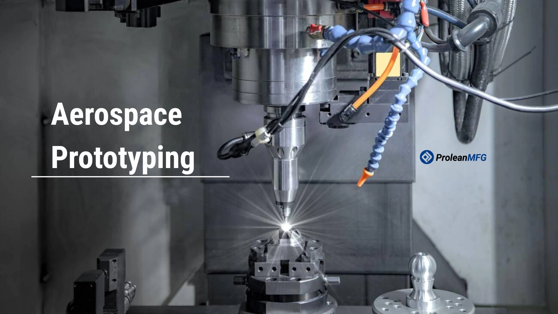

Aerospace rapid prototyping helps engineers evaluate designs, test functionality, and identify manufacturing challenges before production commencement.
Whether you are developing structural components, interior parts, tooling, fixtures, or any assembly aids, prototype parts provide valuable feedback. Additionally, they support practical, cost-effective design iterations in advance.
Several Aerospace Manufacturing techniques support prototype development. These include CNC machining, 3D printing (SLA and SLS), vacuum casting, and sheet metal fabrication, and each process provides unique advantages in terms of material selection, dimensional accuracy, lead time, and part complexity.
However, the right choice depends on the prototype’s functionality and the requirements of the development program. For example, CNC machining is usually selected if part tolerances are required near close to +/-0.005 inches or better.
This article will walk you through the common aerospace prototyping methods. You will learn about their advantages and limitations, and how they are used to support design verification, functional testing, tooling development, and low-volume production.
So, keep on reading.
What Is Aerospace Prototyping?
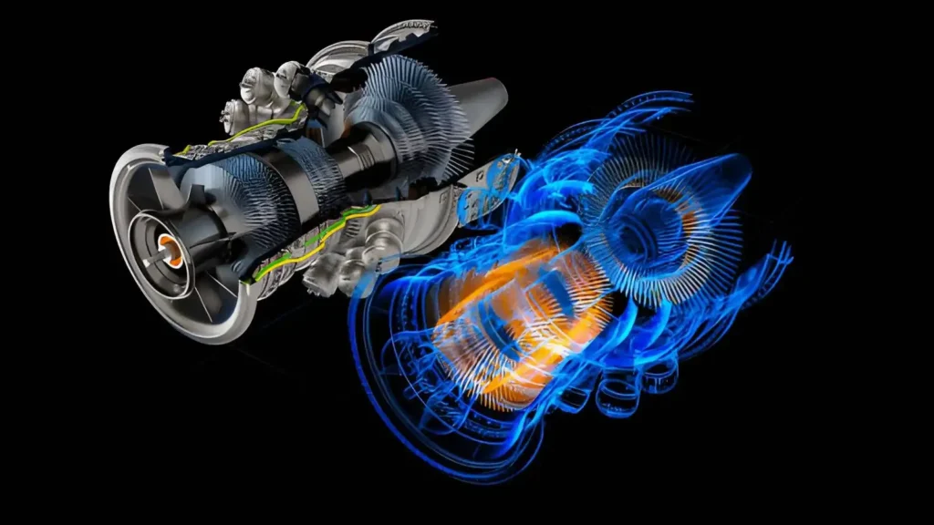
Rapid prototyping in aerospace involves creating prototype parts and tooling for products before entering full production. The primary objective is to assess fit, assembly, functionality, and detail requirements (i.e., design) with actual parts rather than solely relying on computer-aided design (CAD) models and simulations.
Components produced in aerospace prototyping applications can be found throughout an entire aircraft and space vehicle.
They provide engineers with a way to assess assemblies, test proposed design modifications, test new materials, and identify problems that cannot be easily seen in a product’s model on a screen. There are many ways to develop prototypes based on their intended purpose. These include:
- Aerospace CNC Machining
- 3D Printing Aerospace
- Sheet Metal Fabrication
- Vacuum Casting
- Aerospace Injection Molding
Prototyping does not always mean creating only prototype parts. Often, development programs also require fixtures, jigs, gauges, assembly tools, and testing equipment to perform evaluations and pre-production activities.
By building these items early in the process, development teams can refine both the product they are developing and the methods they plan to use in production.
What are the Stages Involved In Aerospace Prototyping?
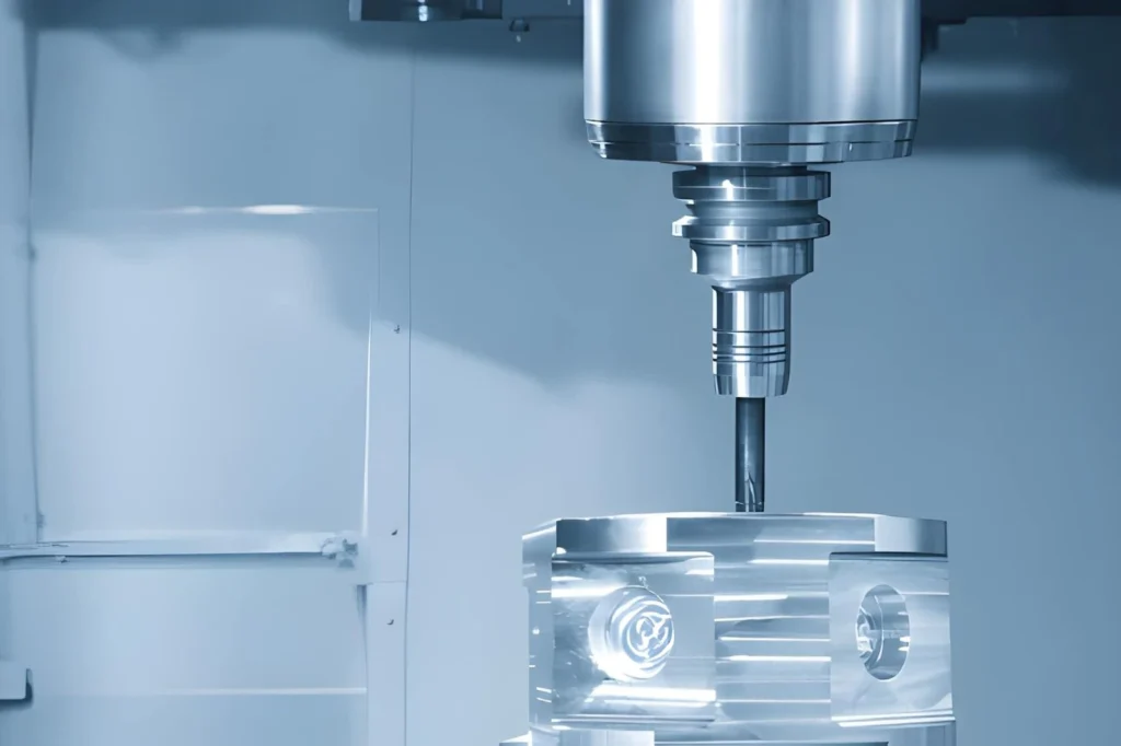
Aerospace prototypes are typically developed through several stages, from the initial design review to functional testing. The exact workflow depends on the component, but most projects follow a similar path before production approval.
Design and Engineering Review
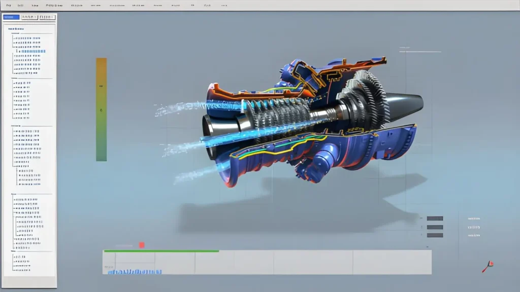
The first stage of aerospace prototype development includes reviewing CAD designs and engineering drawings to ensure dimensional accuracy, interface compatibility for assembly, material requirements, and manufacturing restrictions, before investing time in producing prototype parts.
Material Selection
Aerospace rapid prototyping development requires the use of various materials. The choice of material is generally determined by the type of prototype being created.
However, in prototype development, the major issues normally stem from mismatches between the material and the actual application requirements. For example
- Choosing a material that is not suitable for the actual working conditions.
- Selecting materials that are too expensive too early in the development stage.
- Ignoring manufacturability during the selection process.
Aluminum prototypes are primarily considered as cost-effective, lightweight structural materials in aerospace applications.
In contrast, titanium, stainless steel, engineering-prototype plastic, and composite materials have also been successfully used in aerospace prototyping due to their high performance and ability to withstand various types of testing.
Digital Validation
Before creating a prototype, many engineers use simulation software to model and analyze how different combinations of performance criteria, such as stress, heat transfer, airflow, and vibration, affect the system’s operation.
Identifying design issues early in the process can save considerable amounts of money and resources compared to identifying them after the manufacture of physical prototype parts.
Prototype Manufacturing
Following virtual validation of the system’s performance, the next stage of aerospace prototype development is to create one or more functional test units. As previously mentioned, the method chosen to produce the unit will depend upon its intended function.
The most common machining methods for producing functional metal test parts are CNC milling and CNC turning. However, the intended method may depend on the desired shape of the part.
For example, 3D printing in aerospace can be used to create complex geometries that conventional machining methods cannot easily produce. Sheet metal fabrication can help develop test prototypes for custom enclosures, brackets, and assembly fit.
Assembly and Fit Evaluation
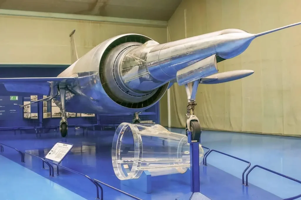
When multiple parts comprise a single assembly, each part will be assembled and inspected individually to verify proper fit-up. This is particularly important to check the clearance between mating surfaces and any specific fastening methods specified during design. At this point, the designers may become aware of potential design modifications that could have been identified earlier had they worked directly with actual parts rather than digital models.
Testing and Design Refinement
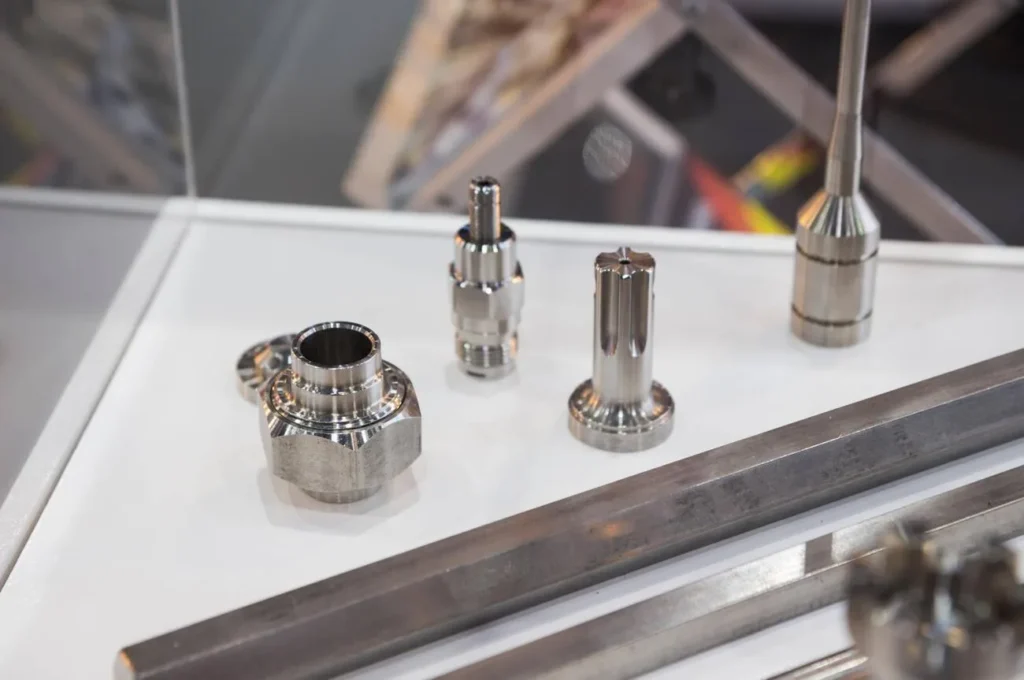
Upon completion of prototype manufacturing, the finished test unit(s) will undergo evaluations relative to the original project specifications. Evaluations may include dimensional inspections and/or functional tests.
Additionally, evaluating environmental conditions and testing complete assemblies are common. Depending on the outcome of these evaluations, the designer may elect to make further changes to the design before initiating pilot production or final manufacturing.
How to Choose the Right Material for Custom Aerospace Prototype Parts
Before you select your aerospace material, you must know what type of prototype it will be used for. There is a significant difference between assembly evaluation and structural, thermal, or environmental testing.
Before choosing the material, define how the prototype should demonstrate the design’s features or the application of rapid prototyping in aerospace industry.
Consider the Service Conditions
A large number of aerospace components are subject to temperature fluctuations, vibration, mechanical loading, and corrosive environments. The prototype material should similarly reflect these conditions where practicable.
Aluminum alloys (e.g., 6061-T6) are commonly selected for lightweight structural parts, while titanium alloys (e.g., Ti-6al-4v), stainless steels (e.g., 17-7PH), and engineering polymers (e.g., Ultem 1000) are selected for more demanding applications.
Match the Material to the Manufacturing Method
Not every material can be fabricated using every prototyping process. CNC machining supports a wide range of aerospace metals and plastics, while additive manufacturing and composite fabrication may provide advantages in complex geometries and lightweight structures.
The selection of a material should be based on the chosen manufacturing route.
Consider Production Intent
For early design reviews, manufacturers frequently use substitute materials. This approach helps reduce costs and lead times. As development progresses, prototype materials generally approach production specifications, making test results more reliable indicators of the final product.
Validate the Material Before Production
The material performance should be verified by inspection and test. Depending on the application’s requirements, this could include dimensional verification, load testing, thermal evaluation, corrosion evaluation, and assembly trials. These results will help determine if the material remains appropriate for the next phase of development.
Which Manufacturing Techniques are Commonly Used for Aerospace Prototyping
Aerospace prototyping encompasses various manufacturing techniques based on the prototype’s geometric configuration, the materials involved, and the stage of development. For aerospace, more than one technique will typically be employed over time throughout the early design phase, validation phase, and pre-production phases.
Aerospace CNC Machining
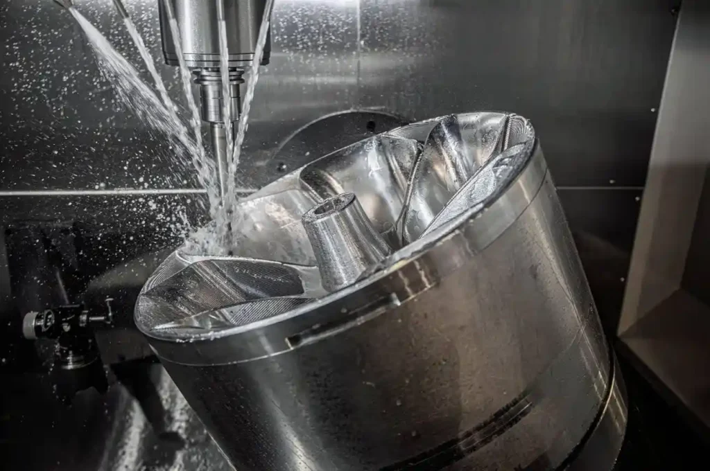
CNC Machining is primarily used to produce metal and engineered plastic prototypes with characteristics similar to those of production-grade material stock. CNC Machining is frequently utilized for bracketry, housing, structural members, and interconnecting hardware components.
CNC Machining is well-suited for designs that require verification of both internal strength and assembly alignment, and it can machine a solid block.
3D Printing Aerospace
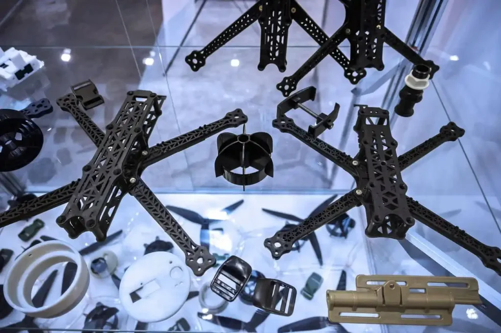
3D Printing is generally employed in the early design stages to allow rapid changes of geometry. It’s an additive manufacturing aerospace prototyping process and helps create complex internal geometries, lightweight configurations, and support rapid design iterations.
Two common 3D printing technologies used for aerospace prototypes are:
- SLA (Stereolithography): It builds parts by curing liquid resin with a laser. It is commonly used for concept models, appearance prototypes, and design review parts that require fine details and smooth surfaces.
- SLS (Selective Laser Sintering): SLS builds parts by fusing powdered material layer by layer with a laser. It is commonly used for functional prototypes, fit-check parts, and assembly validation components that require greater strength.
Designers use 3D printing to perform form studies (to evaluate the overall shape), fit checks (to determine whether mating components can be assembled), and airflow/packaging evaluations (to identify potential issues with airflow or packaging before investing in machined parts).
Aerospace Sheet Metal Fabrication
When the ultimate configuration of a specific component is expected to be a fabricated part (e.g., a bracket, panel, duct, or enclosure section), sheet metal fabrication processes are used. These processes, including cutting, bending, and forming, are used to verify bend allowances, assembly clearances, and fastener locations before developing production tooling.
Vacuum Casting
In instances where multiple identical plastic housings or covers are required (such as for design reviews or functional mock assemblies), Vacuum Casting is typically used. Vacuum casting involves creating a master pattern of a part, making a silicone mold from the pattern, and then casting the part utilizing polyurethane resins.
Aerospace Injection Molding
Injection Molding is used in later stages of development as the design evolves towards production. It is used to validate mold flow, wall thickness performance, and part-to-part consistency under conditions similar to those found during injection molding production.
Typically, prototype runs utilizing injection-molded parts are short-duration and limited in scope, serving only to validate that the design will perform as intended after investing in full-scale tooling.
Manufacturing Methods: Selection Guide
The table below shows the main considerations and when to choose each manufacturing method.
| Process | When to use it | Typical part Application |
| CNC Machining | When the part needs accurate dimensions and real metal or plastic properties | Brackets, housings, structural parts |
| 3D Printing (SLA /SLS) | When the design is still changing, and the part shape is complex and needs quick testing | Fit-check parts, concept models, airflow models |
| Sheet Metal Fabrication | When the part is designed as a bent or folded sheet | Panels, enclosures, brackets, ducts |
| Vacuum Casting | When a few plastic parts are needed without making expensive tooling | Small batch covers, housings, and visual models |
Aerospace Quality Certification and Inspection Control
Aerospace parts often require stringent quality control measures because many end up in assemblies whose failures could put lives at risk.
Because of this, most suppliers are judged on two criteria:
- Their ability to produce the desired product
- Demonstrated control over all aspects of the production process from start to finish.
Below are the typical aerospace certifications and standards practiced in aerospace prototyping services.
AS9100D Quality System
The AS9100D is the primary quality standard for aerospace manufacturers. Based on ISO 9001, AS9100D requires more stringent controls for production planning, risk assessment, inspection records, and purchasing/supplier relations. Specifically, AS9100D outlines in detail how work shall be recorded, inspected, and approved before shipment.
When aerospace customers evaluate potential suppliers for machining or fabrication, they typically require that the supplier be certified to AS9100D. The customer desires assurance that the selected supplier adheres to established procedures for controlling production releases, inspections, and non-conforming products.
ITAR Compliance for Defense Programs
The International Traffic in Arms Regulations (ITAR) regulate defense-related parts and impose restrictions on the use of data, drawings, and completed parts. Only authorized individuals have access to controlled technical data, and exports of technical data follow prescribed approval routes.
As a result of these regulations, suppliers who wish to participate in defense programs must limit system access by approved personnel, establish processes for the controlled exchange of documents, and conduct regular audits of their processing activities related to defense programs.
As a general rule, ITAR compliance is required whenever parts are used in military or defense applications.
In-Process Inspection and Monitoring
Inspecting is not limited to the final product. Critical dimensions and features are measured throughout the production process.
A common method for monitoring the accuracy of a CNC program or additive build is to measure critical dimensions and/or verify the presence of specific features early in the production process, so corrections can be made if deviations occur before completing a full batch.
Dimensional and Functional Verification
Completed parts are verified using measuring equipment, including CMM systems, gauges, and optical scanners. The focus of these measurements includes geometric characteristics, tolerance limits, and surface fit with other components.
Additionally, if the parts have functional requirements, simple load or assembly tests may be performed to verify functionality.
Traceability Across Production Batches
Each batch produced contains tracking information, including certifications issued by suppliers for materials received, records generated by machines involved in processing those materials, and logs documenting the operators responsible for producing each batch.
These tracking elements allow each part to be traced back to its source, including the “heat number” of the raw materials, the specific machines utilized to manufacture each part, and any inspection results obtained for each part. Tracking is essential for supporting both audit activities and for maintaining historical documentation for aerospace programs.
Prototyping Support for Production-Ready Parts From Prolean MFG
Our rapid prototyping services support early validation of geometry, fit, and function before moving into full-scale manufacturing. This allows you to confirm design intent, select suitable processes, materials, and produce parts without delays during later stages.
At Prolean MFG, we build precision-critical aerospace parts using Aerospace CNC Machining Service, sheet metal fabrication, and advanced 3D printing, intended to your project requirements. Each part is produced with defined inspection steps and material control to support engineering evaluation and batch readiness.
If you are developing aerospace components and need quick, controlled prototype manufacturing, our team can support you from initial design through low-volume production with clear process planning and inspection support. Contact us for a free online quote!