Understand the interface
Review current path, clamping force and mating component.
CUSTOM PARTS / ENGINEERING & MACHINING
A contact face must seat flat. A threaded port must be clean. We plan C110 machining, deburring and finishing around the surfaces that carry current or transfer heat.
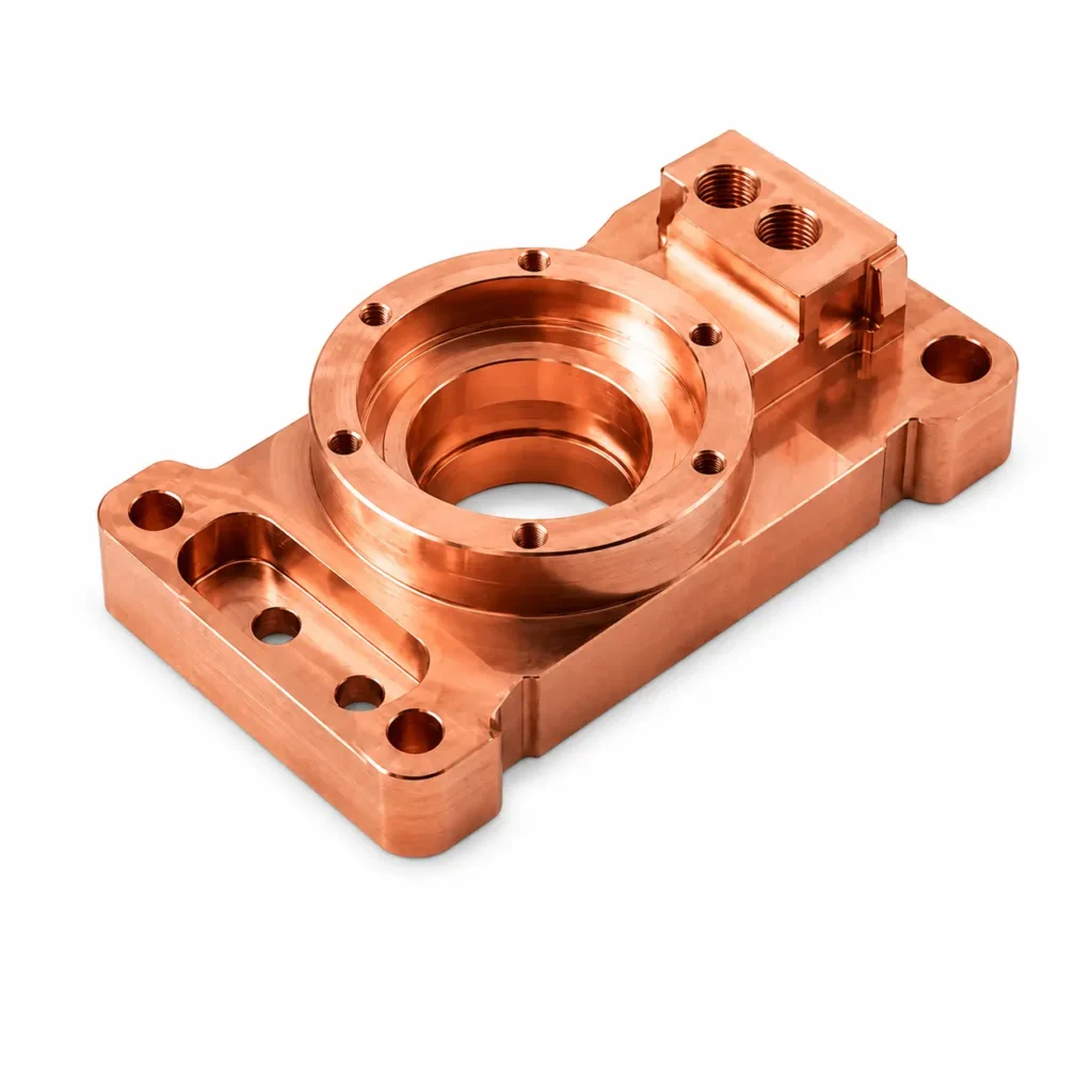
Our review links the feature that matters in your assembly to the proposed setup, machining sequence and acceptance check.
| Your part challenge | Our proposed approach | How to verify the result |
|---|---|---|
| A contact face smears or carries burrs | Plan tooling, workholding and edge control around the soft copper surface. | Inspect the defined contact area and burr limits after cleaning. |
| A thin thermal plate loses flatness | Review balanced removal and support without crushing the part. | Measure released-part flatness using the agreed support method. |
| Plating changes threads or contact faces | Define finish boundaries, masking and final-fit allowance. | Check the finished interface and coating requirements separately. |
ILLUSTRATIVE ENGINEERING BRIEF
Illustrative RFQ: 50 blocks, 60 × 40 × 12 mm envelope, four M4 positions and a 0.05 mm contact-face flatness target before the agreed finish.
These numbers describe an example customer requirement, not a completed customer project or a guaranteed machining limit. Final feasibility is confirmed from the drawing.
Clamp marks and burrs can reduce the useful contact area. A flatness report alone does not demonstrate electrical resistance in the final assembly.
Proposed acceptance: contact-face flatness, thread checks, burr acceptance and finish documentation. Assembly resistance testing is separately specified.
Review current path, clamping force and mating component.
Plan support, chip handling and final surface passes.
Define plating and bare-contact boundaries.
Agree any electrical or thermal validation in addition to machining checks.
Confirm the grade after the functional requirements are clear.
Confirm copper designation, temper and product form. Electrical or thermal requirements should be tied to the specified material and finished interface.
| Material option | Selection context | What to confirm |
|---|---|---|
| C11000 / ETP copper | Conductive and thermal interfaces | Confirm standard, temper and supplier certificate. |
| Specified oxygen-free copper | Applications with different material requirements | Treat it as a separate designation and approved material choice. |
Material reference: Material or fabrication reference ↗.
No. State the assembly conditions and required electrical test if contact resistance must be verified.
Mark the areas and dimensions on the drawing so masking and final acceptance can be proposed.
Use the exact designation and standard. C110 ETP and oxygen-free copper are separate material choices.
The example is a customer brief used to explain the proposed engineering route. Actual limits, cost and timing are confirmed from the complete drawing.
Send the CAD and drawing revision, exact grade, quantity and the critical requirements discussed above. Include mating-part details and required inspection records.
ENGINEER YOUR NEXT PART
Send the drawing and tell us which feature controls assembly, sealing or motion. Our review connects that requirement to a proposed route and inspection scope.