
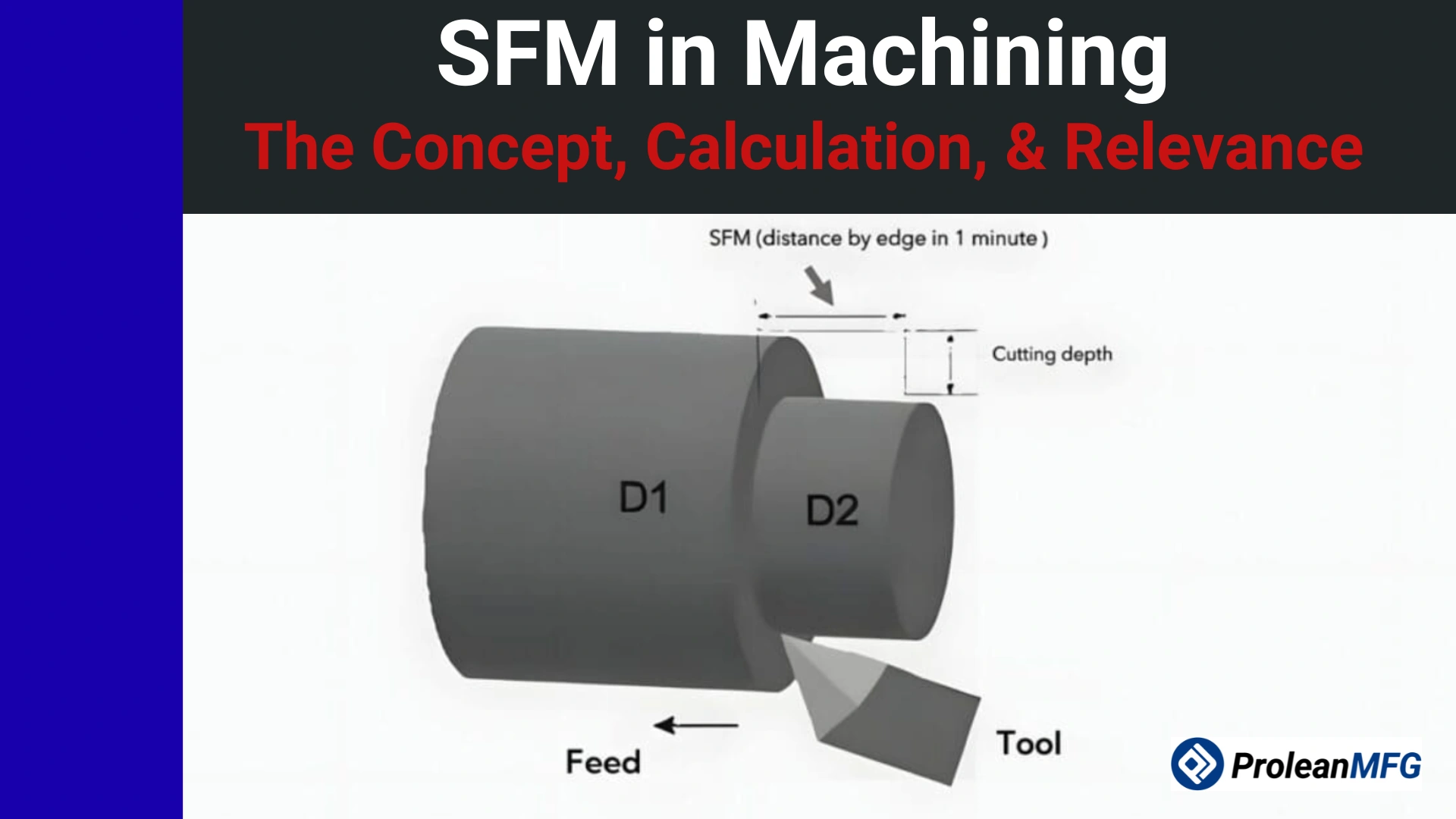

SFM is a CNC machining parameter that refers to the speed of the cutting tool’s edge relative to the surface being machined. The speed is used to determine the most effective spindle speed for different combinations of tooling and materials.
Every workpiece material has an optimal surface footage range, which is based on a balance of tool performance and machining speed.
When cutting speeds in machining are off even by the smallest margin, cost overruns can affect machining operations. Machinists may have to contend with dimensional inaccuracies, overheating, faster tool wear, chattering, and other machining issues.
Understanding SFM (Surface Feet per Minute) in machining helps in optimizing CNC machine performance. The machinist can optimize tool life, select the ideal spindle speed, and match cutting requirements to different materials.
The next sections of this article cover SFM in more detail, including its importance, factors affecting the parameter, recommended SFM for different materials, SFM calculation, and more.
What is SFM in Machining?
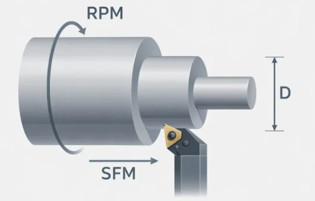
SFM in machining is an abbreviation for surface feet per minute, a parameter for the movement of the cutting tool edge relative to the workpiece surface. In other words, SFM defines the relative velocity between the workpiece and the cutting tool during a CNC machining operation cycle.
Note that SFM is different from spindle RPM. Spindle RPM simply describes how fast the spindle turns, while SFM is a linear measurement.
What are the Units Used to Measure SFM?
Surface footage can be measured in either millimeters per minute (MM/min) or feet per minute (FPM).
Millimeters per Minute (MM/min): This is the international or metric-based measurement system. Users or machinists in the US may need to convert the metric measurements to the more common one – FPM.
Feet per Minute (FPM): Feet per minute (FPM) is the standard measurement in the US. FPM needs to be converted before it can be used internationally.
Why Correct SFM Matters in CNC Machining?
Running the correct SFM is one way to optimize costs and ensure part quality. SFM should be neither too high nor too low.
When SFM is too high, the dangers include dimensional instability and thermal damage. When SFM is too low, it can cause work hardening on some alloys and a poor surface finish.
So, when you meet a supplier who consistently delivers tight tolerances with low scrap rates, know that they are most likely getting it right with SFM.
Factors that Affect SFM Selection
When selecting SFM, consider the tool material, tool coating, tool diameter, workpiece material, machine rigidity, coolant quality, and operation type. These elements are documented and controlled for every machining job.
1. Coating and Tool Material
High-Speed Steel (HSS) tools typically cut more slowly than carbide tools. That’s mainly because they tend to lose their hardness when the temperature exceeds 600°C. For carbide tools, the hardness is dependable to approximately 1,000°C, so they can sustain higher SFM.

Since tool coating acts as a thermal barrier, it extends the temperature barrier. Therefore, a manufacturer still relying on uncoated tools is missing out on the benefits of enhanced SFM.
2. Tool Diameter
From the mathematical relationship RPM = (SFM × 3.82) ÷ D, which can be used as an RPM to SFM formula, the desired SFM is directly dependent on the tool diameter. This relationship is critical because it implies that vibration and breakage are likely to occur in smaller-diameter cutting tools rotating at high RPM.
The following table aligns common tool sizes to SFM.
| Tool diameter | 100 SFM (Steel) | 300 SFM (Stainless) | 800 SFM (Alum) | 2000 SFM (HSM) |
| 1/8″ (0.125) | 3,056 | 9,168 | 24,448 | 61,120 |
| 1/4″ (0.250) | 1,528 | 4,584 | 12,224 | 30,560 |
| 1/2″ (0.500) | 764 | 2,292 | 6,112 | 15,280 |
| 3/4″ (0.750) | 509 | 1,528 | 4,074 | 10,186 |
| 1.0″ (1.000) | 382 | 1,146 | 3,056 | 7,640 |
| 3.0″ (Face Mill) | 127 | 382 | 1,018 | N/A |
Source: [1]
3. Workpiece Material
The machinability of a material affects SFM because of related factors such as hardness and thermal conductivity. For instance, for a material like aluminum that dissipates heat quickly, it is easy to reach higher SFM (up to 1,500) compared to Inconel (up to 100).
4. Machine Rigidity
Machine rigidity is an SFM in machining consideration because it relates to chatter and vibration. A setup with poor workholding or excessive tool overhang must go with low SFM for cut stability.
High SFM may work perfectly on an advanced, well-maintained machine, but it is a liability in an aged machine.
5. Coolant Strategy
Coolant strategy determines how effectively heat generated during cutting is managed. Sufficient flood coolant keeps the cutting tool below its critical level and allows for higher SFM, unlike dry cutting.
6. Operation Type
The SFM targets are different for roughing and finishing operations. For roughing, a moderate SFM is good enough, coupled with a higher depth of cut and feed rate.
Finishing requires higher SFM, but the depth of cut is lower. That’s because finishing prioritizes dimensional accuracy and surface finish.
Recommended SFM for Materials
Common materials in CNC machining have their typical SFM ranges. For instance, one of the most widely machined aluminum alloys supplied under ASTM B221 specifications [3], ranges from 600 to 1,500+. Other CNC machining materials worth highlighting are mild steel, alloy steel, tool steel, stainless steel, cast iron, titanium, and brass/bronze.
| CNC Machining Material | Typical SFM Range |
| SFM for 6061 Aluminum | 600 to 1,500+ |
| SFM for Mild Steel | 200 to 500 |
| Alloy steel | 200 to 400 |
| Tool steel | 100 to 300 |
| Stainless steel | 150 to 350 |
| Cast iron | 300 to 600 |
| Titanium | 100 to 250 |
| Brass/bronze | 400 to 800 |
[2]
Milling SFM Chart
Milling operations usually have an SFM chart, with specific values varying by tool engagement and type of machining operation. The following table captures the values for carbide end mills under standard operating conditions.
| Material | Side milling SFM | Slotting SFM | Finishing SFM |
| Aluminum | 800 to 1200 | 600 to 900 | 1,000 to 1,500+ |
| Mild steel | 300 to 450 | 200 to 300 | 400 to 500 |
| Alloy steel (4140) | 220 to 350 | 180 to 250 | 300 to 400 |
| Stainless steel (304) | 180 to 280 | 120 to 200 | 250 to 350 |
| Titanium | 100 to 180 | 80 to 120 | 150 to 220 |
| Cast iron | 350 to 500 | 250 to 350 | 450 to 600 |
How to Calculate SFM in Machining
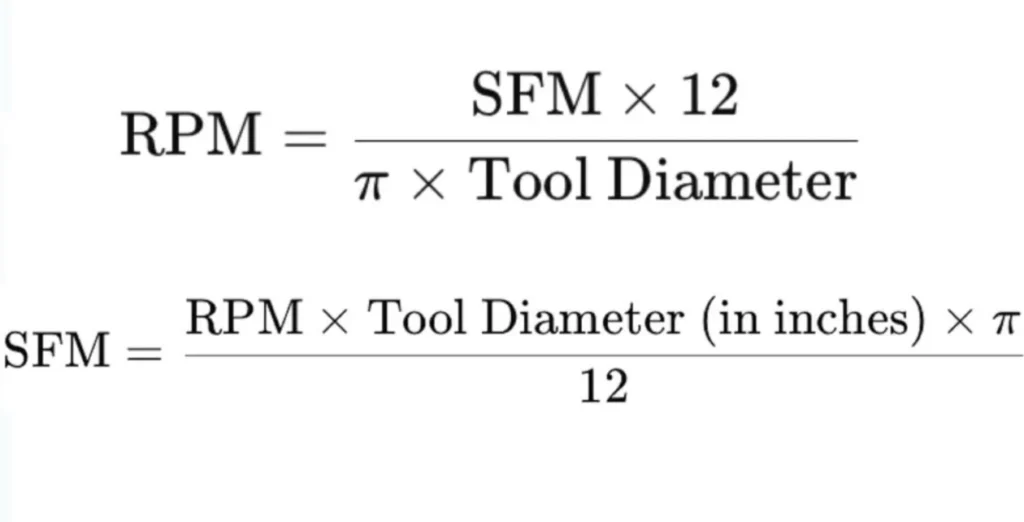
The SFM formula is:
SFM = (RPM × Tool Diameter × π) ÷ 12
It can also be written as:
SFM = (RPM × D) × 0.2618
This is a simpler version.
These formulas demonstrate how to calculate SFM and convert surface feet to rpm. They are the standard RPM to SFM formulas. Machinists use the formulas for SFM vs RPM comparisons and conversions.
Tools and Methods for Accurate SFM Calculation
Accurate SFM calculation involves a blend of reference data sources, calculation and programming tools, optimization systems, and process monitoring and feedback systems. Under these categories, you will find elements such as tooling data, CAM software, in-machine tool management systems, and force or load monitoring/feedback.
Reference Data Sources
These include tooling data, manufacturer catalogs, and digital databases and libraries.
Manufacturers provide SFM range recommendations for different materials, machining operations, and tool types.
Machinists also get guidance from manual and digital catalogs. The recommended SFM ranges have been developed through testing.
Modern production facilities can also share crucial data. Some of these facilities have centralized databases that ensure repeatability of machining projects.
Calculation and Programming Tools
From data sources, we go to tools, which comprise calculators and CAM software. SFM calculator milling solutions help derive spindle speed (RPM) from the tool diameter. They can help minimize the machine setup time.
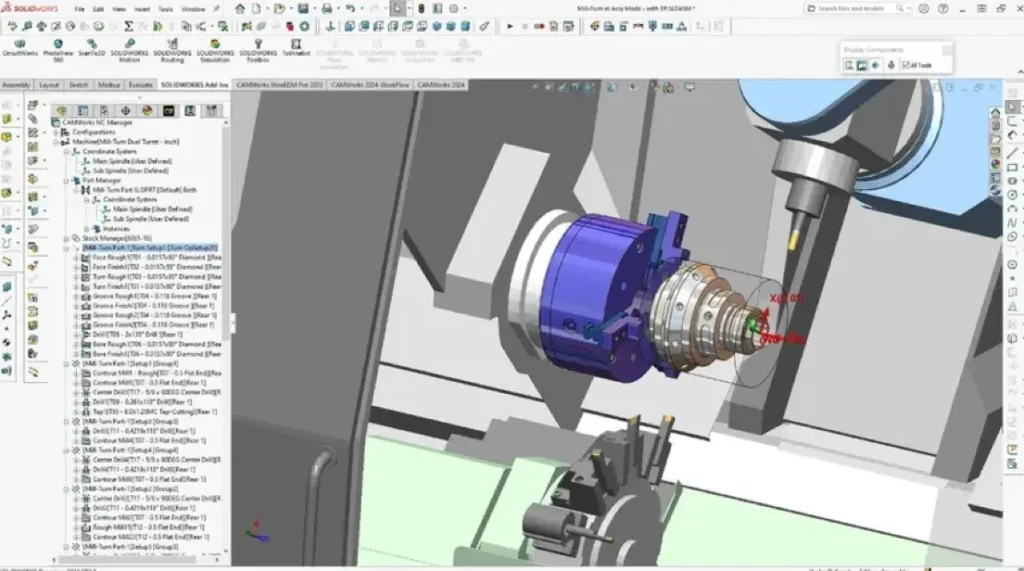
CAM software uses material and tooling data to determine the appropriate cutting parameters. The solution can also be used to generate the machining toolpaths.
Optimization Systems
Machine optimization systems are relevant in tool management and controller feed & speed. Modern CNC machines feature functions that track tooling and apply the appropriate cutting parameters.
Some have advanced controls for adjusting feed and speed. This not only extends tool life but also optimizes machining.
Process Monitoring and Feedback Systems
Whether it is for loading monitoring or real-time monitoring, these systems are instrumental in the optimization of machining parameters and ensuring the health of machinery.
So, as the buyer, it is important to enquire whether SFM values are picked from legacy projects or tooling data.
Is a Higher SFM Always Better?
Not necessarily, because factors such as the machining, tooling, and material can vary. Every combination of these factors has a certain sustainable threshold, beyond which heat generation and tool wear would become unbearable.
The best way to look at surface footage is specific jobs’ requirements for surface finish, tolerances, tool life, and so on.
Consider two materials with varying machinabilities – Aluminum and Inconel. Higher SFM for 6061 aluminum can minimize cycle time and machining costs. But the coolant, spindle speed, and machine rigidity have to be optimized.
Excessive SFM is a recipe for serious failures, including dimensional drift, poor surface finish, chatter/vibration, tool wear/breakage, and thermal damage.
1. Dimensional Drift – High cutting speed increases heat at the cutting zone. Heat buildup causes the workpiece and cutting tool to expand. This triggers tolerance inconsistencies.
Solution: Enhance cooling and reduce the cutting speed.
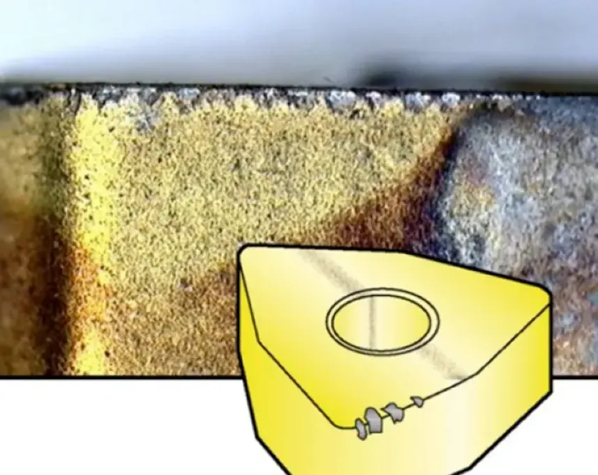
2. Tool Wear/Breakage – Excessive SFM enhances edge chipping and flank wear. In the worst-case scenarios, this can cause catastrophic tool failure.
Solution: Comply with the recommended machining speed
3. Poor Surface Finish – When the SFM is too high, the cutting tool edge tends to be unstable. This can cause visible tool lines.
Solution: Use the correct tooling and feed rate. Also, lower the SFM.
4. Chatter/Vibration – Too high SFM can cause unstable cutting forces and machine-tool harmonics. These are often evidenced by irregular cuts.
Solution: Enhance the machine’s rigidity and reduce the machining speed.
5. Thermal Damage – Excessive surface speed results in localized heating, which can alter material properties.
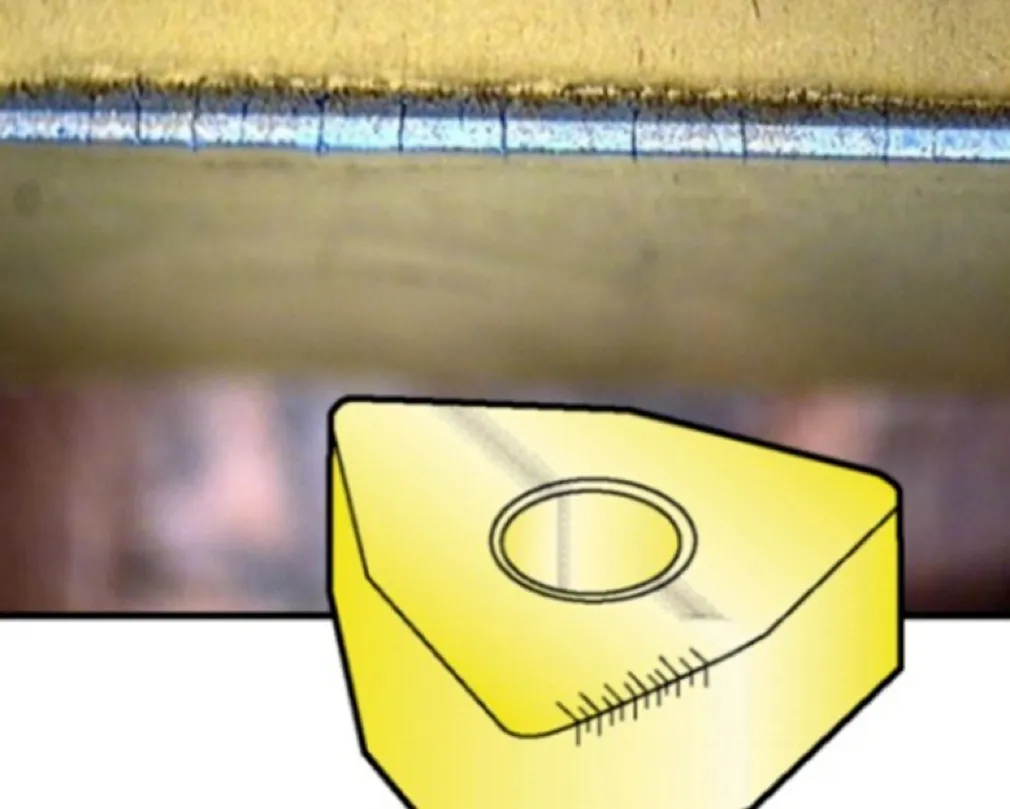
Solution: Use heating-resistant tools and lower the SFM.
These failures indicate that the risks of too-high SFM extend beyond tooling issues.
What Happens if SFM is Too Low?
Issues that can arise from low SFM are poor machining, high tool pressure, heat buildup, and poor surface finish.
- Poor Machining: The machining efficiency is poor when the SFM is low. The cutting tool is prompted to work extra hard.
Solution: Enhance the material removal rate with the recommended SFM
- High Tool Pressure: Since the tool is required to work more aggressively due to low SFM, pressure on it increases. This can even lead to tool breakage.
Solution: Use the optimum cutting speed to reduce cutting forces and strain on the tool.
- Heat Buildup: Like high SFM, low SFM can also cause heat buildup. That’s because the tool spends more time rubbing against the workpiece instead of cutting efficiently.
Solution: Use quality coolant. Increase the SFM for effective chip production.
- Poor Surface Finish: Low SFM can lead to tool chattering, which can affect the surface finish.
Solution: Ensure the machine’s rigidity is adequate and use the recommended SFM level.
What are the Common Mistakes to Avoid in SFM Calculation?
SFM calculation errors can emanate from overlooked tool wear, incorrect unit conversion, ignored manufacturer’s recommendations, incorrect/outdated tool data, and generic data for different materials.
Overlooked Tool Wear
Tool wear is a real challenge, but machinists can sometimes overlook it, which consequently affects SFM and performance. Tool manufacturers usually provide wear recommendations. These guidelines are helpful when determining the amount of SFM to assign.
Incorrect Unit Conversion
The SFM units in the US and the rest of the globe are different. Machinists can convert incorrectly from inches to mm, or even confuse feet and inches. This type of human error can be avoided if an SFM calculator milling or software is used to convert the units.
Misinterpreted Manufacturer Recommendations
Another common SFM calculation mistake is the failure to ensure specific cutting conditions are met for the manufacturer’s recommendations to apply. Machinists should consider using these recommendations as benchmarks. They can then optimize cutting from that point.
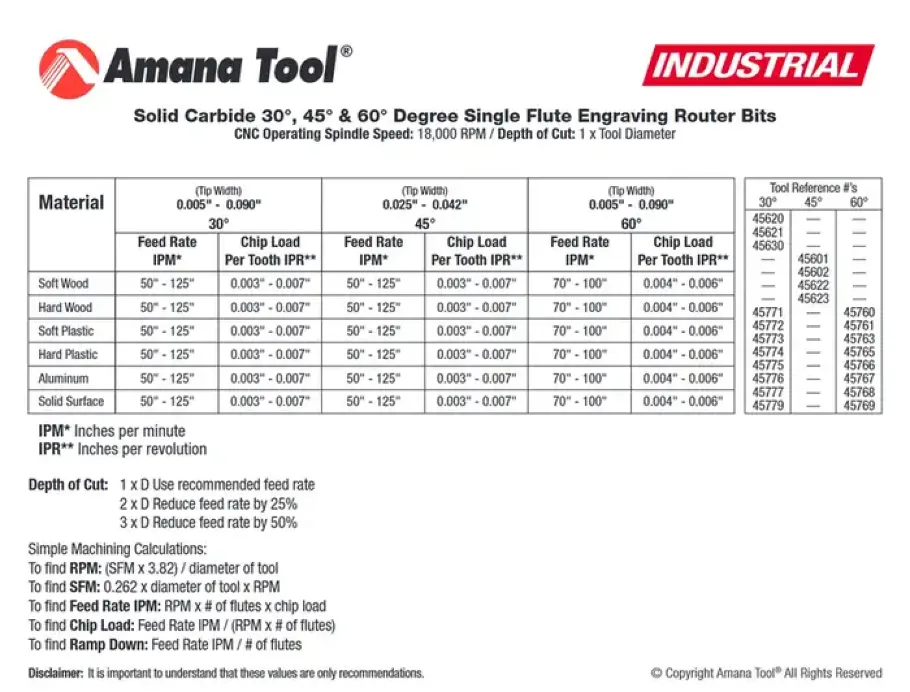
Incorrect/Outdated Tool Data
Data should match the specific tool. This is possible with timely tooling data updating and verification.
Generic Data for Different Materials
It is important to account for material-specific properties when calculating SFM. Failure to do so can affect machining efficiency. SFM settings should be optimized according to the material being machined.
Cutting Speed vs SFM
Cutting speed and SFM (Surface Feet per Minute) are different unit systems for the same physical quantity. If you are focusing on the US market, the common unit is SFM.
For a more direct relationship, if the cutting speed for say, stainless steel, is 120 m/min, that equals 394 SFM.
Is SFM the Same as FPM?
Yes, both SFM and FPM in machining refer to the same thing. FPM denotes Feet per Minute, which, like SFM, is the linear velocity of the tool’s cutting edge relative to the workpiece surface.
However, note that SFM is considered more precise because the measurement is specified to be taken at the workpiece surface rather than at the centerline.
In the American context, machinists and other professionals in the field tend to use SFM and FPM interchangeably.
Common Industrial Applications of SFM in Machining
Popular industries for SFM in machining applications are automotive, aerospace, and medical. Here’s how the solution is applied in the industries.
SFM for Automotive Parts
Using the recommended SFM for materials in the automotive industry enhances cost-effective production and higher production rates.
SFM for Aerospace Parts
In an industry with tolerance requirements up to ±0.0001 inches, getting the right SFM is non-negotiable. The solution is central to the quality of structural components, turbine components, and landing gear parts.
SFM for Medical Devices
Applying SFM in medical device manufacturing ensures excellent material integrity and surface finish. Manufacturers can meet the stringent requirements for biocompatibility and surface cleanliness.
Real-World Application of SFM in Machining
SFM is a real machining parameter that affects performance and economics on the shop floor.
Consider this example: Machining a 4140 alloy steel bracket using a ½” carbide end mill and flood coolant with a bore tolerance of ±0.001″.
- Scenario 1: 380 SFM.
- Scenario 2: 280 SFM.
| Element | Scenario 1 | Scenario 2 |
| Within the recommended range | No | Yes |
| Dimensional drift | High | Low |
| Scrap risk | High | Low |
| Cycle time | Faster | Baseline |
| Total cost per part | Higher | Lower |
Conclusion
SFM is one of the key determinants of success in CNC machining operations. While it may appear to be just a number, this parameter significantly affects cutting speed, precision, and overall process cost-effectiveness.
With coverage of the meaning of SFM, calculation, conversion of surface feet to rpm, and importance in CNC machining, this article has reiterated the need for businesses to seek to understand the concept.
If your parts are coming back with inconsistent tolerances or excessive tool wear, incorrect SFM is often the root cause. Partner with a reputable CNC machining services company and get a free DFM review from experienced machining engineers.
We’ll assess your material, tooling, and cutting parameters and recommend the right SFM for your job. Upload your CAD file and get a quote within 24 hours.
Sources
[1] https://www.cncoptimization.com/resources/guides/sfm-rpm-conversion/
[2] https://community.carbide3d.com/t/rpm-and-sfm-calculations-please/86564
[3]https://www.matweb.com/search/DataSheet.aspx?MatGUID=8b43d8b59e4140b88ef666336ba7371a
[4] https://asm.matweb.com/search/specificmaterial.asp?bassnum=mq304a