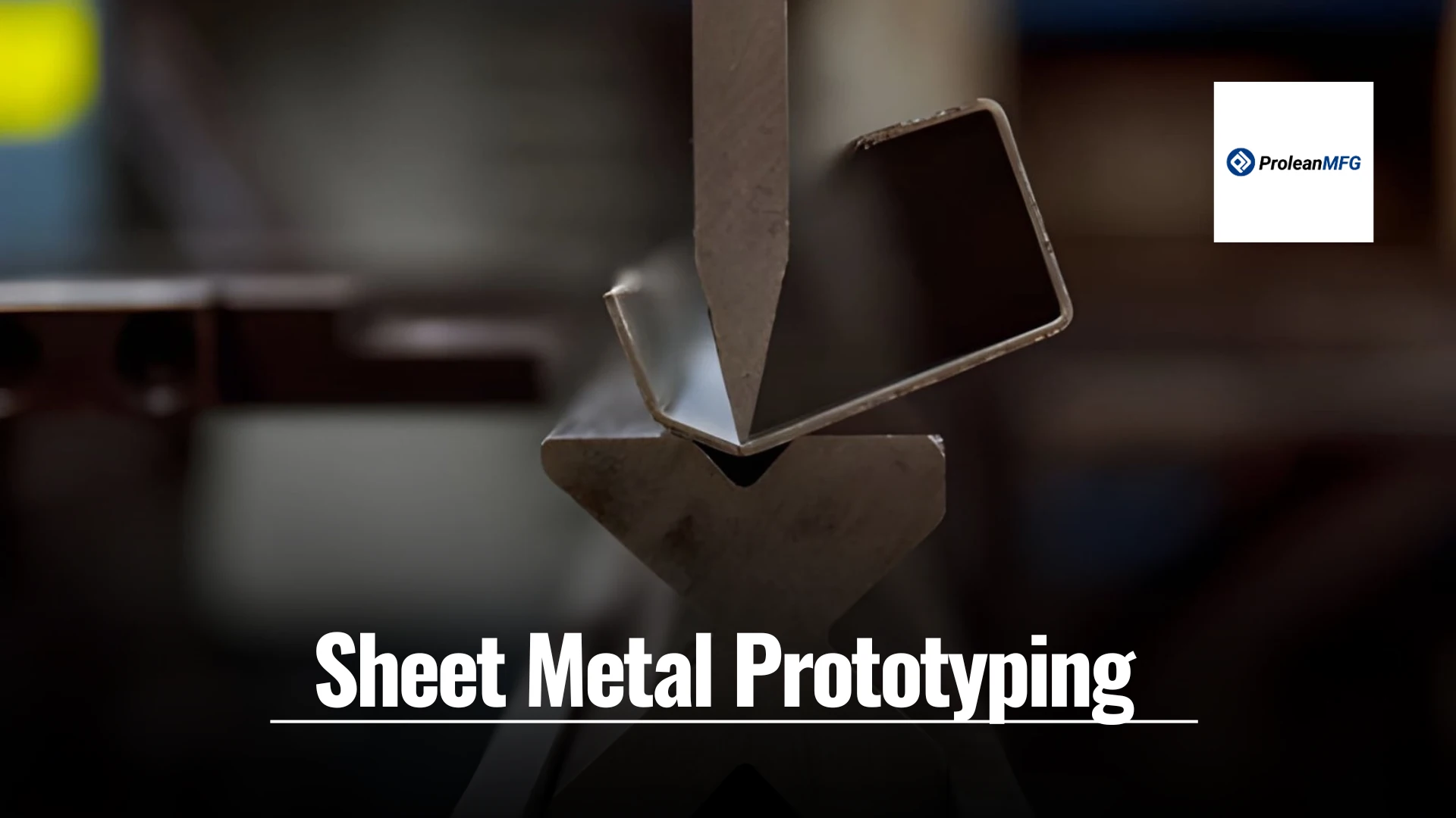

Sheet metal prototyping is used to make genuine parts from the same material and processes as the final product. It allows engineers to check fit, alignment, and assembly in the real world, not just on a screen.
The process usually includes cutting, bending, punching, and welding to produce parts that behave as intended in the final design. Prototypes make it easier to spot interference, weak points, or assembly issues early. Teams can also test small design changes quickly and verify them under realistic conditions.
This approach helps reduce errors, saves time, and ensures the final parts meet functional and dimensional requirements. Explore all about sheet metal prototype fabrication in this guide.
Typical Workflow of Sheet Metal Prototyping
The prototype manufacturing process allows designers to test their concept before investing in full-scale production. Designers can validate how the part will perform, assemble, and fit together as if it were being built on an actual production line. Rapid prototyping sheet metal can be produced quickly and inexpensively by utilizing the same sheet metals and manufacturing techniques that will be used to create the final part.
CAD Design & Prototyping
The first step in sheet metal design of a prototype is to create a CAD (Computer-Aided Design) model. This ensures all the dimensions, angles, and tolerances have been accurately captured. The CAD program will also allow the designer to create flat pattern sheets and simulate bending. This will help ensure that the prototype created meets the specifications of the final design.
Material Choice
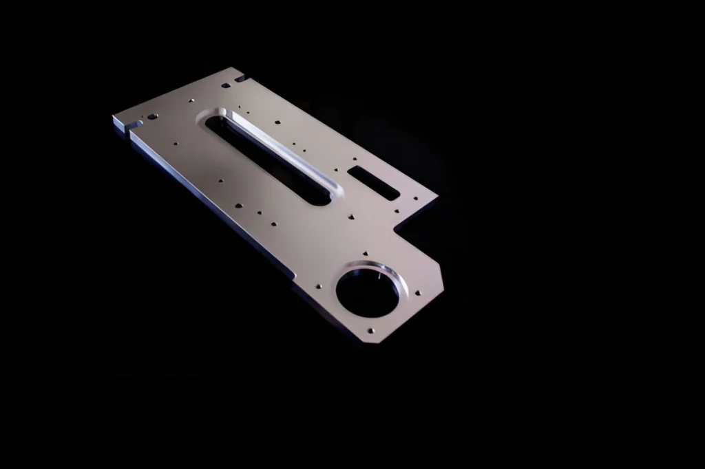
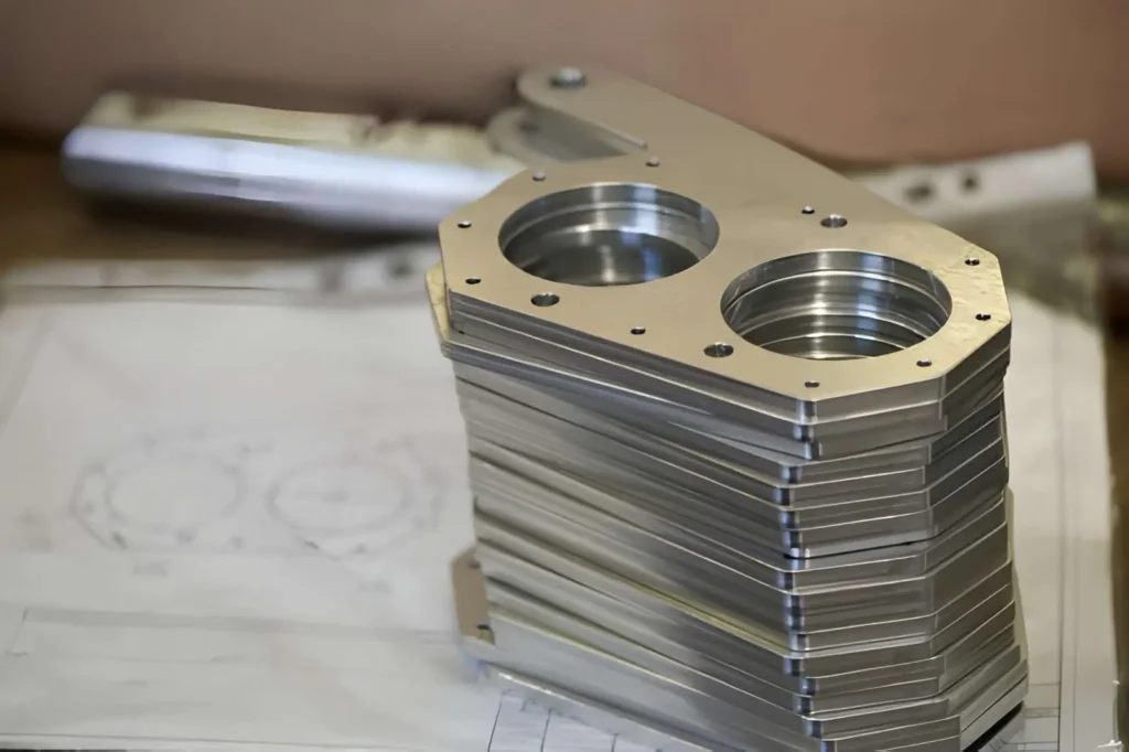
Aluminium sheet metal prototype part
Select a material that simulates the characteristics of the final part. Aluminium, Stainless Steel, and Mild Steel are common choices for strength and flexibility. If corrosion resistance or special characteristics are required, Copper, Brass, or Titanium may be selected. Using the same material as the final part will provide realistic test results.
Materials for Sheet Metal Prototyping
| Material | Common Alloys/Types |
| Steel | Carbon steel, Stainless steel, Galvanized steel |
| Aluminum | 5052, 6061, 3003 alloys |
| Copper | Pure copper, Copper alloys |
| Brass | Copper-Zinc alloys |
| Titanium | Pure titanium, Titanium alloys |
Sheet Cutting
Sheets are then cut to shape using methods such as laser cutting, Waterjet cutting, Plasma cutting, or Shear cutting. Laser cutting offers the most precise cutting method. In contrast, Water Jet cutting eliminates heat damage to the sheet, and Shear cutting is less expensive but works well for simpler cuts during early-stage prototyping.
Bending/Forming
Once the cut parts have been processed, they are bent/formed using Press Brakes, Rollers, or Prototype Dies. It is essential to achieve accurate bends so the parts fit correctly and work as intended.
Assembly/Final Touches
Steel sheet metal parts
Assembled parts are connected using welding, riveting, or fastening. Final surface treatments (such as anodizing, powder coating, chemical film, etc.) can be applied to evaluate the part’s durability, appearance, and performance before entering production.
Sheet Metal Prototype Manufacturing Processes
The rapid prototyping services allow you to create parts using the same materials as the final production components. In addition, the manner in which you cut, bend, or shape the metal will determine the similarity of your prototype to the end product. The type of processes you use depends on the level of detail in the part, the type of metal being used, and the purpose of the prototype.
Cutting Techniques
Laser Cutting
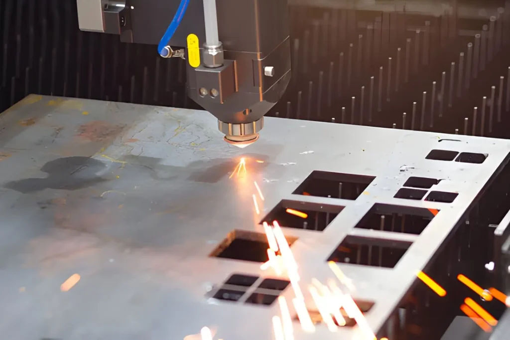
Metal laser cutting
Laser cutting utilizes a highly concentrated laser beam to cut shapes in sheet metal accurately. Laser cutting is best suited for prototypes with fine details or smooth edges, where precision is key.
Water Jet Cutting
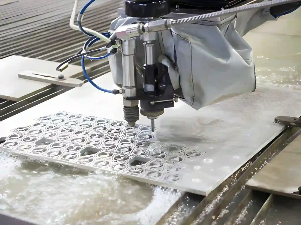
CNC waterjet cutting metal sheet
Water Jet cutting uses a combination of high-pressure water and abrasives to cut through the metal. Water Jet cutting is beneficial when cutting heat-sensitive metals or when using methods that could cause metal warping in traditional cutting techniques.
Plasma Cutting
Plasma cutting is a quick method for cutting thick sheet metal. While plasma cutting is highly efficient, it may require additional finishing to eliminate excessive roughness at the edge.
Shearing
Shearing is a mechanical method for making straight cuts in sheet metal. Shearing is best suited to simple rectangular panels or basic geometric shapes.
Hole Punching and Perforation
Punching removes a small portion of metal to provide holes for fastening, ventilation, or aesthetic purposes. Perforation is similar, except that perforation creates patterns or repeated openings within the sheet metal.
Forming Processes
Standard Bending
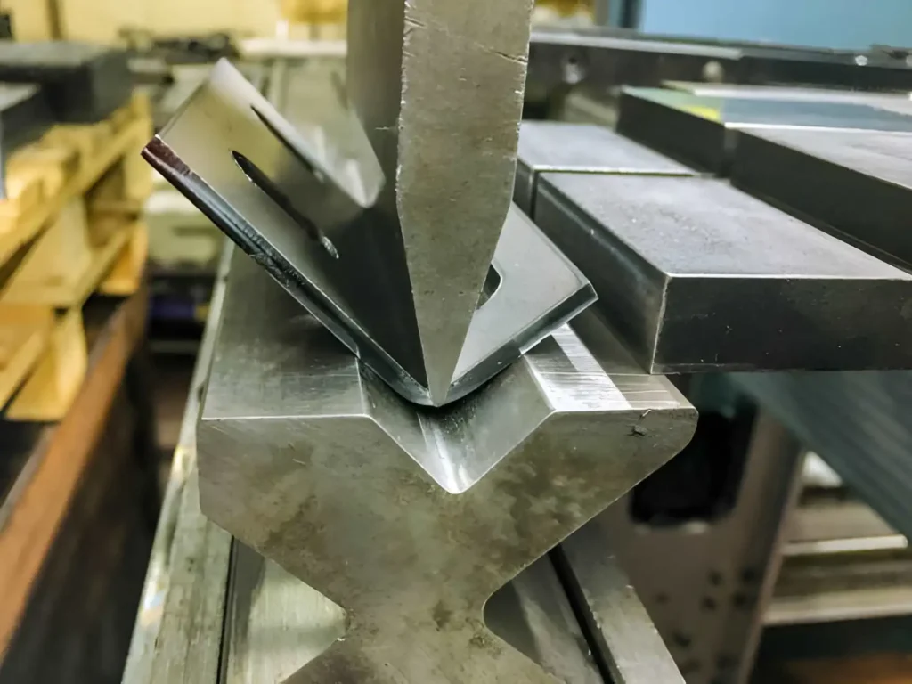
Sheet metal bending machine
Standard bending shapes sheet metal into items such as brackets, frames, or enclosures. Standard bending enables prototypes to demonstrate how the component will operate in its final assembly.
Edge Curling
Curling the edges smoothes them and adds rigidity. This is often done for safety, to achieve a finish, or to prevent sharp edges.
Rolling
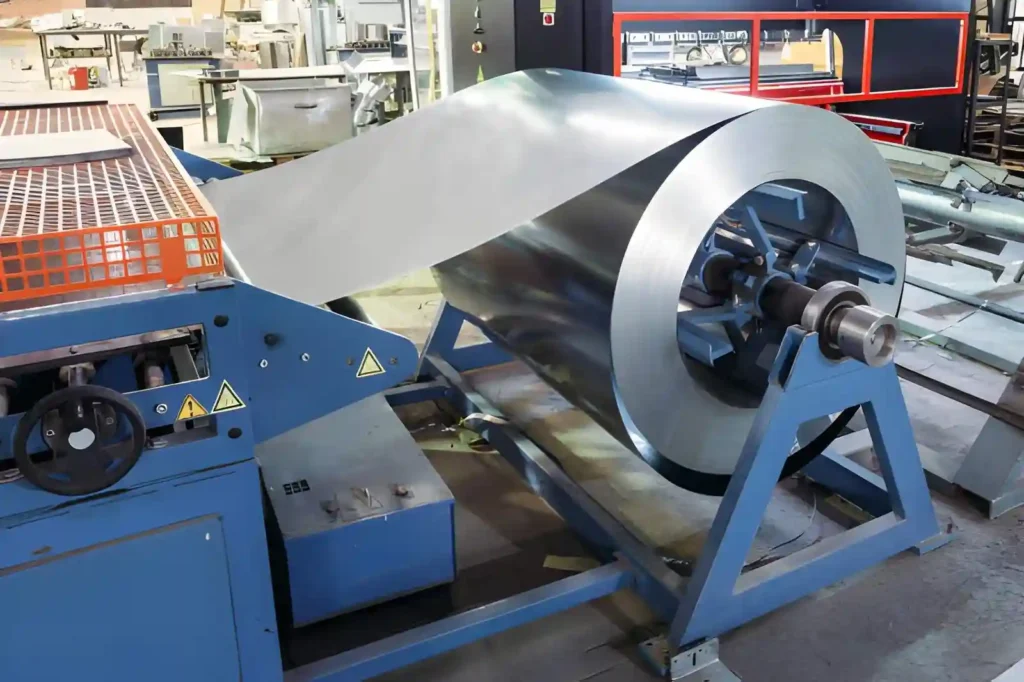
Galvanized steel sheet rolling
Hydroforming
A hydroform press uses a fluid (liquid) to apply pressure to the die to form the metal. The advantage of hydroforming is that it allows complex curved shapes to be formed while maintaining better thickness control compared with conventional stamping.
Forming by Press Brake
A press brake forms metal using a machine to provide precise, angled bends. A press brake is most often used to produce a variety of components with exact dimensions and close tolerances.
Incremental Forming
Incremental forming is a process that gradually deforms sheet metal into a detailed shape. Due to its ease of use, incremental forming is a suitable method for making prototypes, short runs, or one-of-a-kind parts that need accuracy.
Spinning
Spinning is a process in which sheet metal is rotated on a lathe while being formed into a rounded or conical component. Spinning is best for creating symmetrical components, such as cones and cylinders.
Deep Drawing
Deep drawing uses dies to draw metal into concave, cup-shaped forms. Deep drawing is most suitable for containers, housings, and other recessed parts.
Production-Oriented Forming (Occasionally Used for Prototypes)
Stamping
Stamping uses a combination of bending, punching, and embossing to shape metal quickly. Stamping is ideal for creating prototype parts that look like the final product and will eventually be mass-produced.
Roll Forming
Roll forming is a continuous process where sheet metal is passed through a series of rollers to maintain a consistent profile. It is most commonly used for producing channels, rails, etc. Since roll forming is so easy to repeat, it is a great way to make large quantities of similar parts.
Joining and Assembly
- Welding: It joins sheet metal parts for functional prototypes.
- Riveting: Riveting joins two or more sheet metal parts using a metal fastener called a rivet. The rivet is inserted through aligned holes in the parts, and the tail is deformed (usually by hammering or pressing) to create a permanent mechanical joint.
- Mechanical Fastening: Bolts, screws, or clips to assemble sheet metal components.
How to Prepare Sheet Metal Designs for Prototypes
Your primary objective when creating a sheet-metal prototype is to develop parts that mimic the end product but are easily fabricated. As you plan the details of your design, remember to take into consideration the properties of your materials, how they will bend, assemble, and function. This way, your prototype will accurately represent your production parts.
Designing For Efficient Fabrication
All bends, hole locations, and cut-outs should be designed to accommodate standard tools and have consistent radii. Simplify all aspects of your design to minimize errors during fabrication and ensure your prototype closely resembles the actual production part.
Reduction of Stresses at Bends
Bend corners (both internal & external) should be “rounded” to eliminate stresses/weaknesses that may occur due to stress concentration at sharp corners; this will improve the durability of your prototype and mirror real-world performance.
Selection of the Right Material
Choose metals that fit the expected conditions (weight, corrosion resistance, etc.) for your application. The proper selection of materials will enable you to test your prototypes for strength, wear, and usability as they would in the field.
Proper Clearance Between Features
Provide sufficient clearance between all features to allow for unobstructed assembly. Sufficient clearance will provide you with an accurate representation of how your final parts will fit together and function.
Use Standard Sheet Thicknesses
Fabricating with standard sheet thicknesses will reduce fabrication costs and will provide predictable results during fabrication testing (bending/forming).
Limitations of Welds/Joints
Reducing welds/joints will minimize labor required for assembly and will produce a stronger part. Reducing welds/joints will also help you keep your prototype close to the actual production part.
Prototype Should be Designed as Close to Production as Possible
Your prototype should be produced using the same processes and techniques as your production parts. This will allow you to identify potential problems before large-scale production and eliminate the need for redesigns.
Early Collaboration with Your Manufacturer
Collaborate with your manufacturer early in the design process to identify cost-saving opportunities and ways to increase efficiency. Collaborating early will ensure your prototype is manufactured with practical manufacturing considerations in mind.
Speed Up Product Development With Sheet Metal Prototypes
Sheet metal prototyping allows engineers to create functional parts using the same materials and processes as production. By testing fit, assembly, and performance early, prototypes help you identify design issues, reduce errors, and save time.
Prolean MFG helps engineers and designers turn their sheet metal concepts into working parts that accurately reflect how the final product will perform.
We focus on producing functional prototype designs at an affordable price point by identifying practical manufacturing methods for materials and by designing bend, cutout, and tolerance specifications for production.
We combine hands-on experience in creating prototypes with efficient fabrication processes to deliver them in a timely manner, so you can use them as testing tools to refine and validate your designs.
Contact Prolean MFG today for custom sheet metal fabrication services and get a quote on your prototype needs.