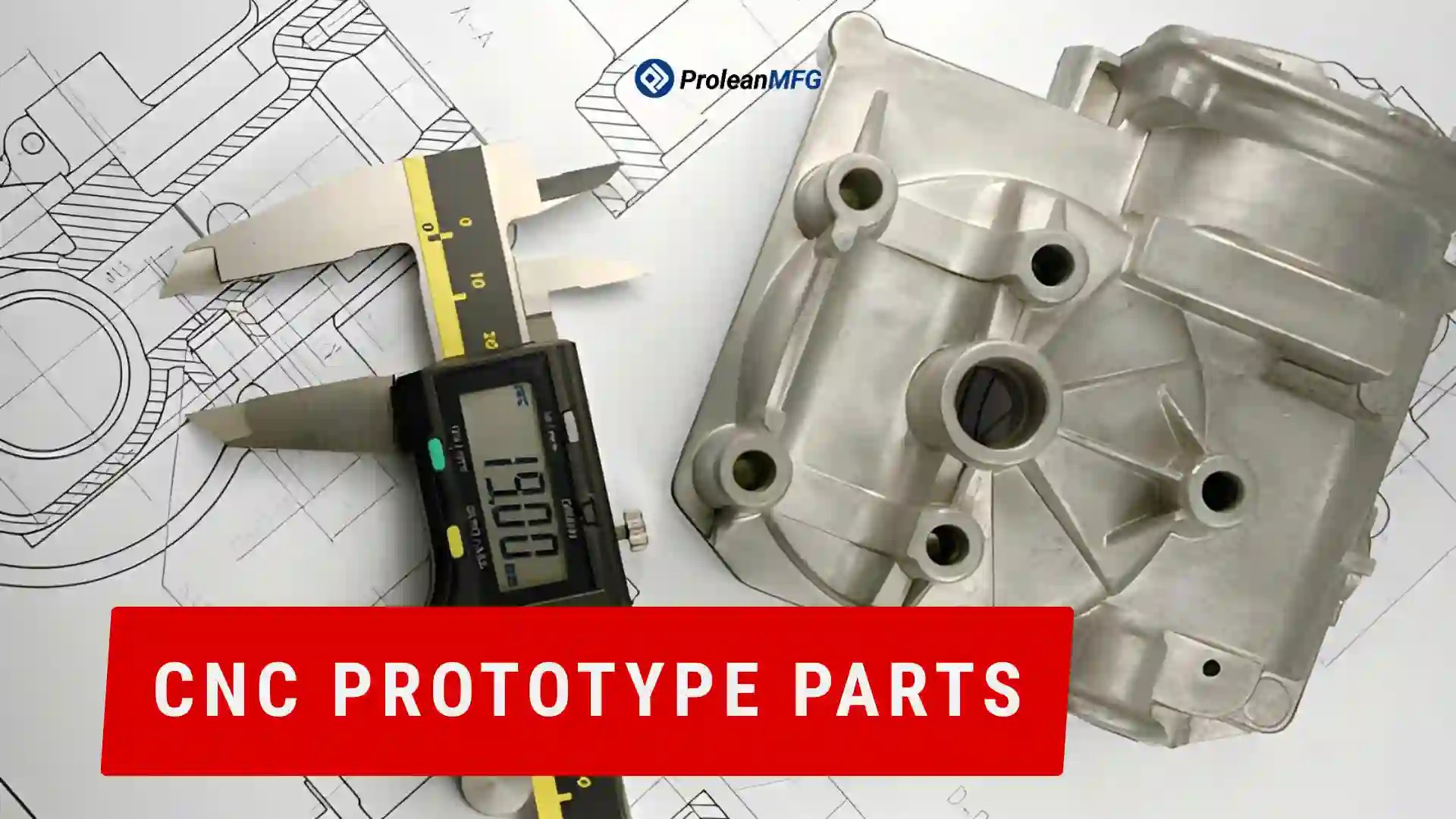

CNC prototype machining is used when engineers need to move from CAD into a real, testable prototype without waiting for production tooling. It allows them to produce small batches of components with exact geometry and stable material behavior.
These prototype plastic parts are created in both form and functional testing. Form is primarily used to test a product’s visual features (shape, fit, finish). Functional testing will provide information on how a product performs under specific loads or in its assembly configuration.
Early in the development cycle, CNC prototype parts can be used to verify that design decisions are correct before moving into higher-volume manufacturing processes. Additionally, they can aid in verifying that parts fit together properly and perform mechanically, and they allow for future design changes.
This article covers the applications of prototype machined parts, how they fit into product development, and the practical advantages and limitations of prototype parts compared to other prototyping techniques.
What is Prototype Part Machining?
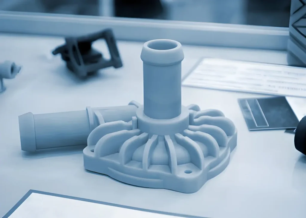
SLA prototype parts
Prototype machining is the manufacturing process that produces small quantities of products or parts from Computer-Aided Design (CAD) drawings using CNC machine tools before producing large quantities. It helps convert a digital model into a physical component that can be inspected and tested for performance during an initial evaluation.
The test components produced are intended to evaluate the product’s design functionality and usability. Some components will be used to visually inspect the product’s form, fit, and finish. Other components will be used to assess the product’s structural integrity, assembly, and operational characteristics under simulated working conditions.
Prototype machined parts allow designers and engineers to identify any potential design flaws earlier rather than later. Making changes in the prototype stage may help avoid costly rework on larger quantities being manufactured.
Prototype Manufacturing for Controlled Production Flow
Prototype manufacturing allows you to create a prototype of your product from your design. In addition to providing you with a tangible version of your product, it also allows you to test and verify that your product works properly, and to check how different components work together (in terms of fit) before starting mass production.
Early Builds
Early builds are used to evaluate the basic design and functionality of a product before moving to later development stages.
During the first few builds, the focus is on ensuring that the fundamental operations and geometric properties of each component function as they should. The prototypes will help you identify any problems with how your products are handled during assembly. In most cases, you can spot flaws and/or make changes to improve performance and functionality at this point.
As such, the goal during early build stages is to identify potential weaknesses in the designs and make improvements as quickly as possible to avoid extensive redesigns later.
Refining Design
The second build phase is focused on refining fit and structure. During this phase, interfaces between components are modified, and the suitability of materials is selected through testing. The design evolves until all functional capabilities are met in simulated assemblies.
Initial Pilot Build Phase
During the pilot build phase, the process of creating initial versions of a product is verified by determining whether its various elements can be manufactured repeatedly. The pilot build phase defines the process, adds inspections, and specifies acceptable criteria. The intent behind conducting pilot builds is to improve production processes and consistency.
Volume Production Phase
The volume production phase is when manufacturing enters a steady state. Manufacturing produces parts in a repetitive cycle. Production focuses on achieving consistent output by limiting uncontrolled changes and ensuring a consistent delivery lead time. In the volume production phase, production runs can be planned and executed repeatedly with little or no variation.
How CNC Prototype Machining Works?
CNC prototype machining is the process of creating a physical product (part) from a CAD drawing using a CNC machine. This technique allows designers to test their designs before they commit to manufacturing large quantities of the products.
Drawing Check and Setup
The first step in creating a product from a CAD drawing using a CNC machine is reviewing the drawing. Reviewing all aspects of the drawing, such as dimensions, tolerance requirements, material selection, and other important features that need to be considered at this point, is critical.
By addressing these factors early, potential problems can be identified before cutting the metal rather than after milling. Depending upon the results of this review, the type of setup method and tooling strategy for milling the part can be determined.
Tool Path Planning
Tool path development is the process of defining the exact path the cutter will take as it mills the part. For simple geometric shapes, tool paths can generally follow straight lines and curves.
However, for complex surfaces or geometries, the area may need to be broken down into smaller segments, each milled independently under strict control. When developing tool paths for areas such as deep pockets or narrow gaps, care should be taken to ensure that the tool remains stable and does not “chatter” or produce undesirable marks on the finished surface.
CNC Programming
A CNC program is developed to instruct the CNC machine. It defines parameters such as the cutter’s travel speed, the depth of cut, and the sequence of operations. In general, the program will include multiple stages of operation to prevent excessive stress on the part being machined and to maintain precision throughout the entire machining process.
Material Selection
When determining which type of material to use with your CNC Prototype Machining, you need to determine what type of testing will be done. If it is just going to test how well something works (functionality), Aluminum is usually chosen because it has properties similar to those of production parts.
If there are no functionality tests planned and you are instead testing the fit, weight, or appearance of the part, then many types of plastic (ABS, PC, PMMA, PP & POM) are good choices.
Machining Process
Prototype machining typically happens in stages. The first stage is rough machining, where the bulk of the raw material is removed relatively fast.
The next two stages are semi-finish and finish, in which progressively smaller amounts of material are removed until the desired surface finish is achieved. By doing things this way, you minimize potential problems caused by end users applying too much pressure to the tools.
Surface Finishing
Once machining is completed, additional cleaning steps can be performed on the part. Sanding removes sharp edges and tool marks. Polishing may also be needed to obtain a very smooth finish.
If a uniform, flat, matte finish is desired, sandblasting may be a viable option. Other coatings (anodizing, plating, or painting) may be added to protect against corrosion or enhance aesthetics.
Selecting a Prototype Manufacturing Route
Each type of production has its own process. The selection of which process to use is determined by testing (how), desired accuracy levels, and current product development status. All processes have established technical limits, and each will produce a different final product.
| Process | Application | Dimensional Capability | Surface Finish | Production Range | Constraints |
| 3D Printing | Concept models, early fit trials | ±0.1 to ±0.5 mm | Layered texture (Ra 5 to 20 µm) | 1 to 50 pcs | Anisotropic strength, visible layer lines |
| CNC Machining | Functional prototypes, assembly testing | ±0.02 to ±0.1 mm | Ra 0.8 to 3.2 µm | 1 to 100 pcs | Higher setup time per revision |
| Vacuum Casting | Small batch production parts | ±0.05 to ±0.3% (size dependent) | Smooth, mold-dependent finish (Ra ~1 to 2 µm) | 5 to 50 pcs per mold | Silicone mold life ~20 to 25 cycles |
CNC Prototype Part Applications
The test parts aid in verifying correct fit within an assembled product, structural integrity, and positioning/alignment of individual components during the initial stages of product development. Here are the typical prototype applications across industries such as automotive, aerospace, medical, electronics, and consumer products.
Medical Industry
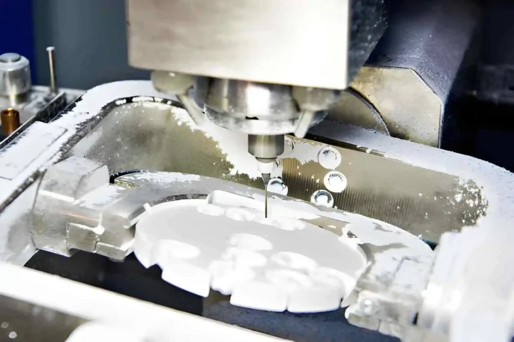
CNC milling dental crown prototype
CNC prototypes are used to verify that medical parts are properly assembled and function as intended during assembly and testing. Commonly manufactured medical parts include device housing, tool body, and fixture components.
Stainless steel has an impressive strength-to-weight ratio. So, it is most commonly selected for medical prototype parts. Plastics are generally used when a lightweight assembly is desired. These parts primarily serve as trial setups and design verification before producing production quantities.
Automotive Industry
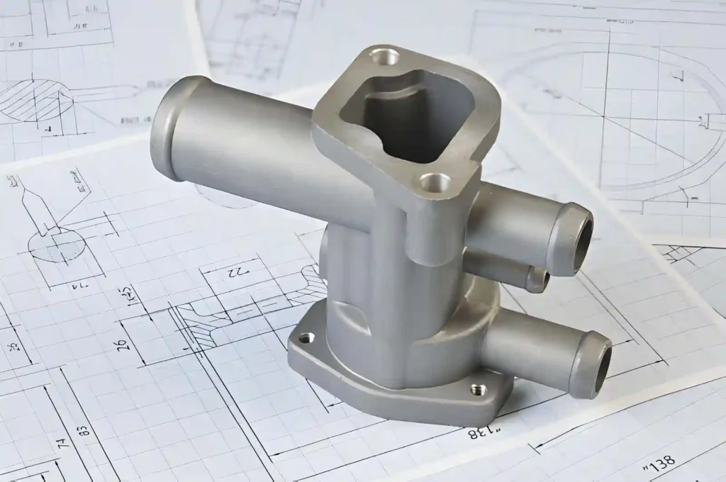
Automotive prototype part
In automotive development, repeated design changes and CNC prototypes enable engineers to make these changes by providing repeatable parts when needed.
Bracket, mounts, and interior components are common parts developed from CAD files to verify clearance, alignment, and fit. These parts typically require several iterations before the final design is completed.
Aerospace Industry
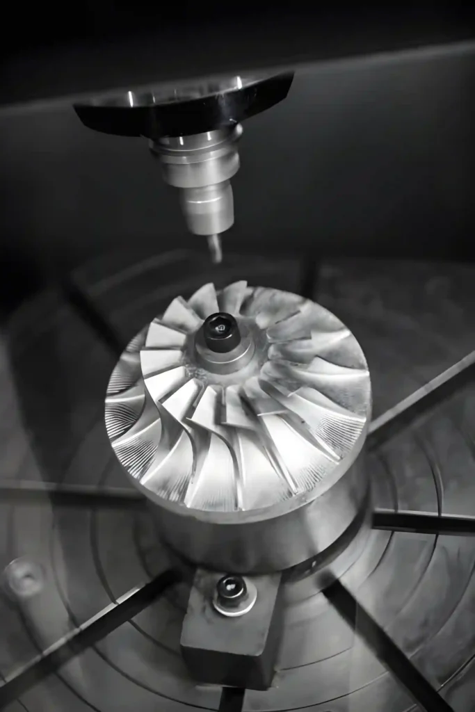
CNC milling jet engine blades
Brackets, ducts, and mounting components are typical aerospace prototype parts examples. The minute dimensional variances associated with each part are verified during repetitive assembly trials. This helps ensure proper alignment and overall system integration.
Defense Industry
Defense industries use CNC prototypes to verify the mechanical and structural aspects of related products. Typical prototype part examples include:
- Equipment enclosures
- Transportation-related parts
These prototypes undergo numerous testing cycles to verify long-term reliability and stability under normal operational conditions.
What Actually Drives Prototype Parts Cost and Lead Time?
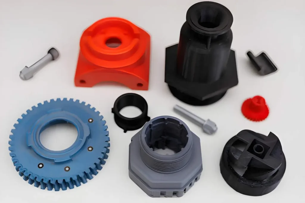
Complex shape plastic prototype parts
The main factors that affect the cost and lead time of a product are the amount of initial setup (or “setup” work) required to produce it.
For example, if you have a very basic product shape and your raw materials’ dimensions remain consistent, it will move through production quickly.
If, however, your product has many complex shapes and features, there will be additional tool changes and increased fixturing checks, which in turn increase the overall machining time. Additionally, small-batch orders typically require more machine setups than larger orders, resulting in longer lead times per part due to the cost of repetitive machine setups.
Lead time can also be affected by the material type used. For example, soft aluminum is relatively easy to cut through. At the same time, hardened steel and reinforced plastic are slower-cutting materials that may add time to the process and cause excessive tool wear.
How Does Material Selection Affect Delivery Speed?
Machining materials that are easier to machine will result in a faster production time. This is due to aluminum and low-carbon steels being processed at a rate that maintains tooling stability during the cutting operation.
Hard alloys (tool steels) and filled plastics, such as stainless steel, require lower feed rates to prevent excessive wear on the cutting edge.
In addition, machining surface finish can also impact processing time. A raw machined product has the fastest delivery time. With each additional required station (bead blasted, polished, anodized, or coated), the overall lead time increases.
Why Do Tolerance and Inspection Increase Project Time?
Tighter tolerances mean greater control in the manufacturing process; therefore, operators will be forced to make their passes at lower speeds to achieve accurate cuts.
Additionally, the operator will have to inspect the part more frequently as it is produced. Besides the production phase (the actual making of the part), inspection can add delay to your project. Depending on how precise you want your part to be, inspection may be limited to visual inspection.
However, if precision is core, then inspectors would use measurement devices such as CMMs or micrometers.
What Details Actually Speed Up Prototype Manufacturing?
A clean machine shop floor plays a big role in how quickly you get your parts. Using an accurate CAD model with a good history will help you avoid problems in your setup.
Keeping only the important dimensions marked in the CAD drawing makes it easier for the machinist to focus on those specific features rather than checking every detail of the design.
Planning and organizing your quantity (the amount you want) is also very important. Knowing exactly what you need (how many parts) will help you plan and prepare your fixtures as well as the tools needed to make them.
Additionally, if the parts are assembled, knowing the exact sequence of steps needed to assemble the product can eliminate trial fits during production.
What You Receive With Every Order From Prolean MFG
At Porlean MFG, the new build is created using the approved revision drawing, so it will exactly meet what you have defined. Critical features are checked during the building process, and before prototypes are shipped or released to you.
Depending upon your quotation requirements, inspection records are added to provide evidence of the checks that were specified when quoting for your project. In doing so, this provides additional transparency into how we build your product.
When initiating a prototype or low-volume build, please share your CAD files and current drawing pack with us. You should include in your submission details on the target quantity, critical dimensions, and any testing requirements. So, we can accurately determine the best manufacturing route and inspection plan for your specific project needs.
In general, we use CNC machining for low-volume to bulk volumes, vacuum casting for small plastic batches, and 3D printing for early prototype development. Lead time and material depend on the process, part complexity and volume requirements.
Our team supports rapid prototyping services, CNC machining, vacuum casting, and 3D printing with a clear path toward repeat production and scaling when needed.