

Sheet metal cutting is a basic process used in many industries to shape flat metal into usable parts. It is commonly used in automotive, construction, and general fabrication work.
There are many ways to cut sheet metal, from simple hand tools to powered machines. The method depends on the thickness, shape, and required accuracy of the cut.
For basic work, tools like hacksaws and tin snips are enough. For faster and cleaner cuts, power tools such as electric saws, nibblers, or rotary tools are commonly used.
Straight cuts are easier and can be done with saws. Curved or complex shapes usually require nibblers and smaller cutting tools. In production environments, sheet metal is cut using processes such as blanking, which cuts flat shapes from a larger sheet. These methods are chosen based on speed, accuracy, cost, and finish quality.
Material type also matters. Softer metals like aluminium are easier to cut, while harder materials require more controlled cutting methods.
This article explains how to cut sheet metal using common cutting methods, the tools used, and how each process is applied. It also covers selecting the right method based on material, cut quality, and production requirements.
Sheet Metal Cutting: Definition and Process Overview
Sheet metal cutting is a material removal process for separating or shaping flat stock into specific geometries. It is commonly used in precision sheet metal fabrication, stamping, and CNC operations.
This process converts flat stock into parts through mechanical or thermal cutting methods. The most common processes are shearing, blanking, laser cutting, and Plasma Cutting.
Selecting which Method to use is based on multiple factors, including the thickness of the Material, the type of material being cut, the required tolerance, and the edge quality of the cut.
For example, thin sheets of 0.05″ to 0.125″ can be cut using tin snips or shears, while thicker sections are generally best suited to laser or plasma cutting.
Multiple cutting operations may also be utilised depending on the geometry. Shearing is most commonly used for straight cuts; however, when making complex profiles with tight tolerances (+/-0.1mm or better), it is generally best to use CNC laser cutting.
Dimensional accuracy, burrs formed, and surface finish (edge roughness or clean cut zones) are all key considerations during the implementation of this process.
How To Cut Sheet Metal in Practice
Sheet metal cutting involves a series of steps, from material selection to the entire cut process. Each step will affect the accuracy of your cuts, the surface finish of each edge, and the overall production speed.
Material Selection and Part Requirements
The first step in sheet metal cutting is selecting the sheet metal based on the application’s requirements. The most common sheet metal types used for cutting are aluminium, mild steel, and stainless steel. A key consideration when selecting sheet metal is its thickness.
Typically, sheet metal is available as thin as .5mm and as thick as 10mm in standard sheet metal. In addition to sheet metal thickness, you need to consider the geometric shape of the parts you want to make, the required tolerance (e.g., +/- 0.1 mm), and the surface finish of the edges.
Cutting Method Selection
Based upon the material you have selected, its thickness, and the degree of precision you require, you will select a cutting method.
These are the primary methods of cutting;
Shearing: It is primarily used for straight cuts and is ideal for high-volume production.
Metal Laser cutting: It is ideal for applications that require very tight tolerances and/or complex shapes.
Plasma cutting sheet metal: It is typically used for thicker sections (usually greater than 6mm).
Water jet metal cutting: It provides a means to make cuts without generating a heat-affected zone (HAZ).
While each of these methods provides different levels of speed, cost, and cut finishes, there are many other factors to consider, including the size of the equipment and whether it is portable or fixed.
Machine Setup and Parameters
Before cutting, the machine parameters must be adjusted to the specific job. Key machine parameters that should be considered before cutting include:
- Cutting speed
- Feed rate
- Power level (for laser or plasma)
- Tool clearance (for shearing)
Improper adjustments of these parameters can result in burrs, edge deformations, or inaccurate dimension measurements.
Cutting Operation
During the actual cutting process, the machine removes the material along the previously defined path.
Straight cuts are generally faster to produce and easier to control than curved or complex shapes, which require a computerised numerical control (CNC) system. High-precision CNC laser cutting can achieve tolerances of up to ±0.05 mm.
Edge Quality and Finishing
Upon completion of the cutting operation, an evaluation will be conducted to assess the edge finish quality. This evaluation may reveal defects such as:
- Burrs
- Rough edges
- Heat Affected Zones (thermal cutting methods)
Depending upon the severity of these defects, secondary operations such as deburring or grinding may be necessary to improve the surface finish (i.e., Ra 3.2-6.3µm).
Process Control and Accuracy
Accurate cutting depends on maintaining proper setup, using the correct tools, and good operator control. Maintaining consistency in dimension measurements, edge cleanliness, and the ability to repeat results is essential, particularly when producing large quantities.
Common Sheet Metal Cutting Processes
Sheet metal cutting is accomplished using various techniques based on sheet thickness, shape, and the required level of precision. Techniques include those designed for quick straight cuts, for detailed profiles, or for more difficult-to-cut materials.
Shearing
Shearing is primarily used to cut straight lines in sheet stock. A sheet is placed between two blades, and then sheared with an upward motion from the top blade.
Raw sheets are most frequently sheared before additional processing, as they are blanked.
Shearing can be effective in reducing deformation caused by blade clearance (typicall-to 10% of the sheet metal’s thickness). Aluminium, mild steel, and stainless sheet metal can be easily processed, provided the equipment has sufficient capacity to handle them.
Generally, sheared edges have a clean appearance; however, slight burr formation can occur on thicker material. It is relatively fast and capable of producing large quantities of identical straight cuts, but it is ineffective for complicated shapes.
Punching and Blanking
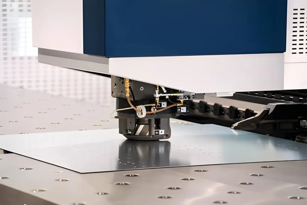
Blanking creates holes, slits, or cutouts. When the punched out portion becomes the finished product, the term “blanking” is used.
Both blanking and punching utilise a punch and die within a press tool. The clearance between punch and die is crucial for obtaining acceptable results.
Typically, the amount of clearance varies from 5 to 12% depending upon the material being processed, its thickness, and hardness. If improper clearance exists, significant edge tearing and/or excessive burrs can result.
Due to their rapid cycle times and consistency of output per stroke, both blanking and punching are widely used across industry, enabling the manufacture of large volumes of parts. Progressive dies are commonly used to produce parts with multiple features created simultaneously in a single operation.
Trimming
Trimming is performed after forming operations to remove excess material from a part’s edges. Trimmed material is typically found on parts that were pressed or drawn deeply. After forming, the edges of these parts do not always lie flat or uniformly. The trim die replicates the part’s final profile, ensuring dimensional accuracy during assembly.
This last step helps maintain uniformity among the components of an assembly. Additionally, it helps minimise variability between produced parts. Specifically, trimming helps control panel dimensions in automotive manufacturing.
Laser Cutting of Sheet Metals
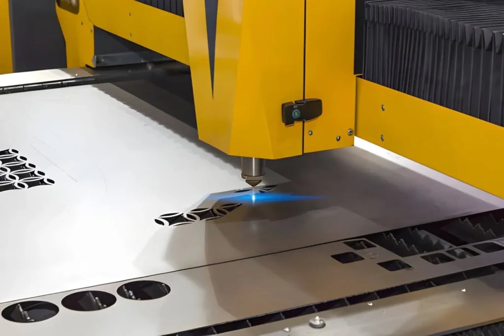
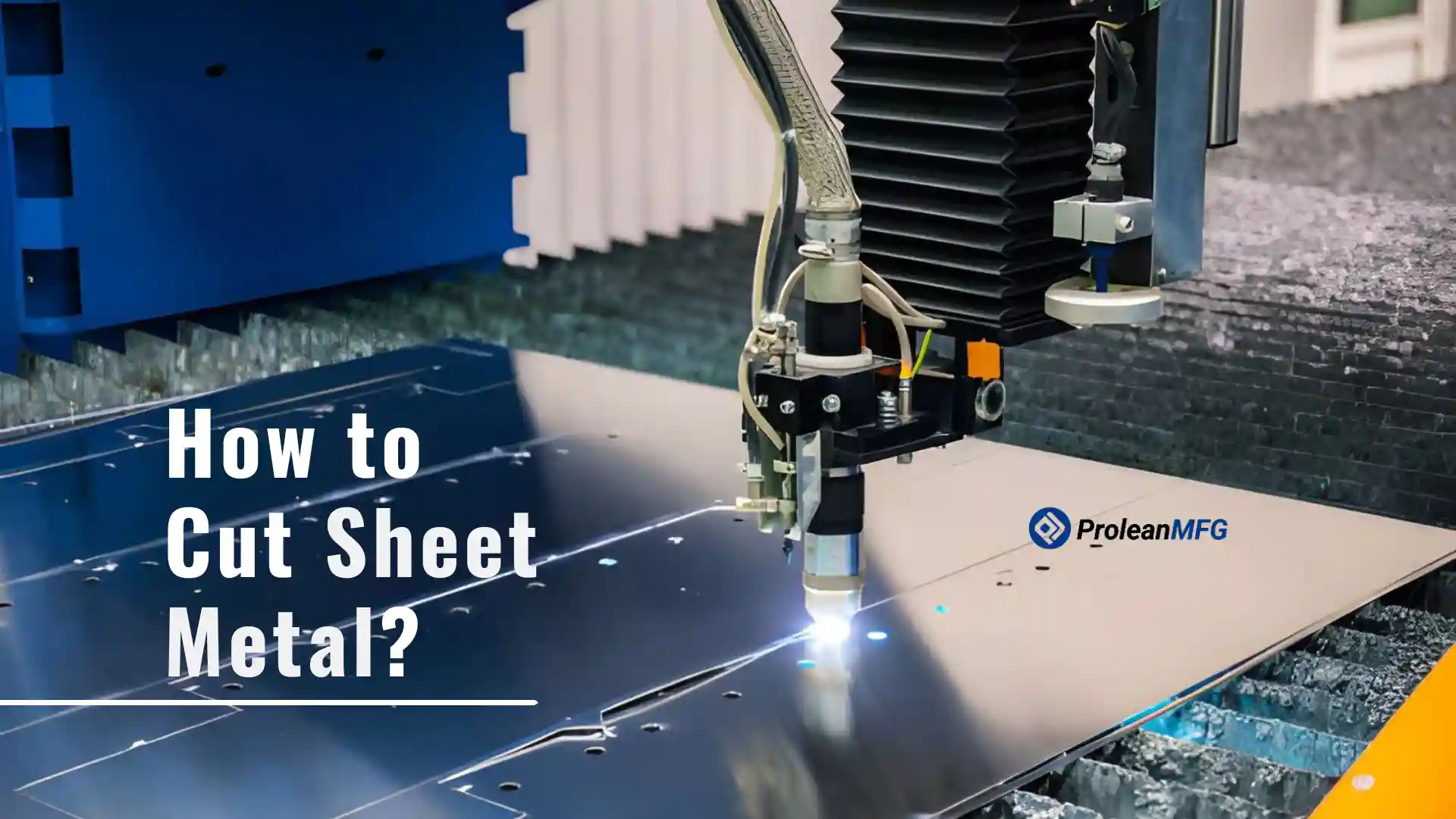
Laser cutting involves melting and removing metal using a concentrated laser beam along a pre-programmed CNC route. Typically, laser cutting is used when dimensionally accurate, geometrically complex parts are required.
Tolerances are typically controlled to ±0.05 mm to ±0.1 mm or as specified by the machine configuration and material. Gases such as oxygen or nitrogen are often introduced to enhance cut quality and control oxidation.
Although the area affected by heat is relatively small, minor discolouration or slight oxidation of the edges may occur depending upon the material and assist used. Thin to intermediate-thick sheets are commonly cut utilising laser technology. As there is no direct contact between the laser beam and the physical tooling in laser cutting of metal sheets. Therefore, it eliminates mechanical tool wear.
Plasma Cutting
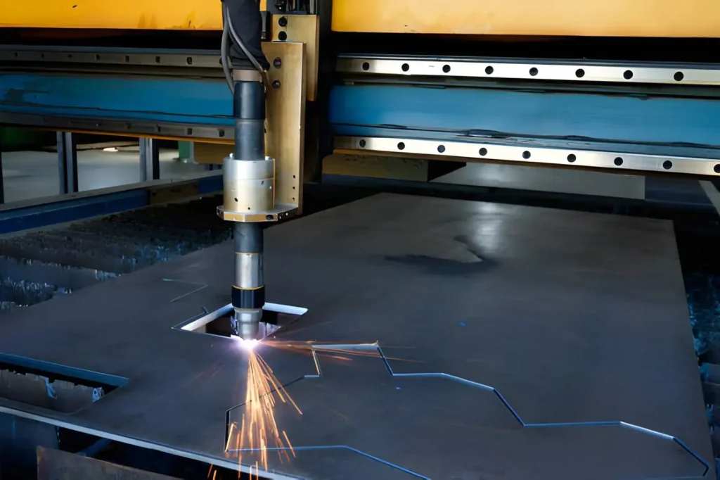
Plasma cutting uses an ionised gas to generate a high-temperature arc that melts and expels metal.
Primarily, plasma cutting is applied to larger-diameter, electrically conducting materials for which laser cutting would be impractical or too expensive. Plasma cutting is very efficient due to its high cutting speeds; however, the resulting kerfs are considerably wider than those from laser cutting.
Additionally, edge finish quality is slightly lower. Heat input to the base material is higher, resulting in a heat-affected zone. Dross forms at the bottom edge of plasma-cut parts and is normally removed during secondary finishing operations. Due to these factors, plasma cutting is a popular choice for structural fabricators working with large diameter pipe and heavy structural steel products.
Waterjet Cutting
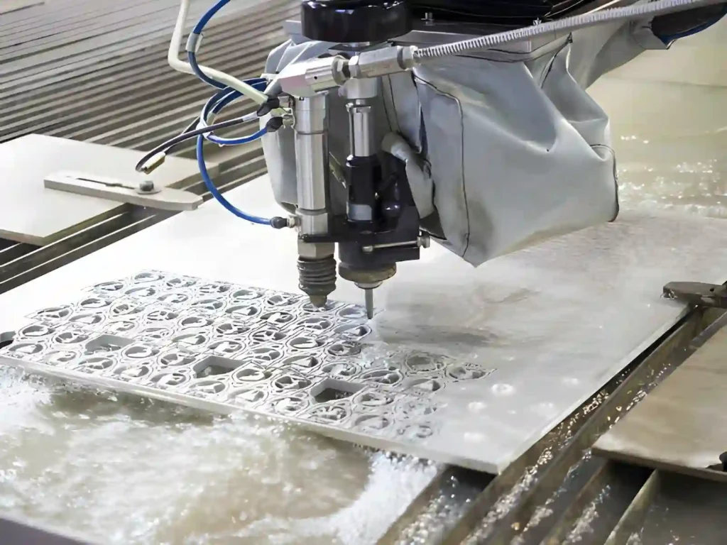
Hydro-abrasive jet machining (HJAM), also known as hydro-jet machining or water-jet machining, employs a combination of high-pressure water flow and abrasives to abrade the workpiece.
The high-pressure water stream (usually 60-90kpsi) carries abrasives that are fed into the cutting head to remove the workpiece material. Since HJAM does not involve heat transfer, thermal distortion or changes to the microstructure of the workpiece near the cut region occur.
Therefore, HJAM can be effectively used for cutting composite materials, ceramic-based materials, large-diameter tubings, and multi-layer materials. While HJAM produces a smooth edge quality similar to laser cutting, depending on the material, wall thickness, and nozzle condition, taper can sometimes be observed on the cut edge.
Although HJAM produces excellent quality cuts, it tends to be slower than other thermal cutting methods and inherently provides more stable quality control.
Angle Grinder Cutting
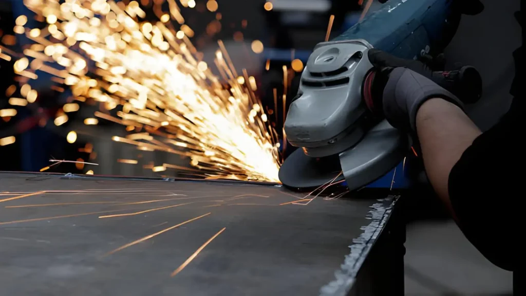
An angle grinder uses a rotating abrasive-coated disc to grind away metal during a grinding process.
Angle grinders are generally used for maintenance and repair jobs involving fittings or other smaller fabrication jobs. Two common types of materials can be cut with an angle grinder. Cutting discs have no reinforcement and are therefore ideal for use on lighter-gauge metals. Reinforced cutting discs, however, contain additional layers that help support heavier metal gauges.
Regardless of the material being cut, the performance of an angle grinder will vary based on the user’s control over the disc’s movement and speed. In addition to varying degrees of distortion caused by the high frictional heat produced by an angle grinder, some metal alloys, such as stainless steel, will also show colouration of their edges when ground with an angle grinder.
While angle grinders offer versatility, they do not lend themselves well to precision applications that require consistent tolerance and high-quality cuts.
Nibbler
A nibbler is a machine designed specifically to punch many small holes along a length of sheet metal. It is often used to produce holes for screws, bolts, and rivets. Thin sheet metal (typically 2-3 mm thick, depending on the metal being punched) is best suited for nibbling.
Compared to shearing thin sheet metal, a nibbler allows operators to cut curved and irregular lines without deforming the sheet.
Additionally, instead of leaving behind a large amount of waste in the form of strips from conventional shear cutting processes, a nibbler produces relatively short chips. De-burring after cutting is usually unnecessary, and the edge quality is excellent.
Saw-Based Cutting
Circular saws and reciprocating saws are among many saw types that can be equipped with carbide-tipped or bi-meged blades to make cuts in sheet or section material.
Saws are typically used for making straight cuts or for creating rough shapes. Blade rotation speed, as well as tooth design, significantly impact quality and heat generated during cutting. Excessive feed rates can lead to premature wear of blade teeth or irregularities in cut edges.
On-site fabrication and repair work are typical areas where saws are commonly used since they offer alternatives when CNC machinery is unavailable. Precision is moderate; however, finishing operations are often required post-cutting.
Deburring
Deburring removes the roughness and the cut ends (edges) that may remain from metal-cutting processes. It can be performed manually with various hand tools and grinding wheels, or with large industrial tumbler-type machines, depending on production levels. The amount of burr formed will depend on both the cutting method and the material being cut.
The importance of this process includes ensuring proper fit and safe handling. In high-precision applications, deburring is typically followed by edge chamfering or other surface finish operations.
Process Selection
- No single method cuts across all possible applications effectively.
- Shear cutting is generally limited to producing straight blanks.
- Punch cutting is generally limited to creating holes in areas where multiple identical holes are needed.
- Laser cutting provides the tightest tolerances and is best suited for cutting complex shapes.
- Plasma cutting is most effective for cutting larger cross-sectional areas at higher speeds.
- Water jet cutting is chosen when there is a need to avoid heating the part due to thermal expansion/contraction.
Selection is made based upon thickness, required tolerance, edge condition, and production level.
Summary of Sheet Metal Cutting Processes
| Process | Suitable Thickness | Typical Tolerance | Edge Quality | Speed | Heat Effect | Typical Use Case |
| Shearing | Up to ~6 mm (depends on machine) | ±0.2 mm | Fair, light burr | High | No | Straight blank cutting, sheet sizing |
| Punching | Up to ~6 mm | ±0.1 mm | Good, but possible | Very High | No | Holes, slots, repeated features |
| Blanking | Up to ~6 mm | ±0.1 mm | Good | Very High | No | Final parts in mass production |
| Trimming | Formed sheet parts | ±0.2 mm | Good after forming | High | No | Edge correction after forming |
| Laser Cutting | Up to ~20 mm (material dependent) | ±0.05 – 0.1 mm | Very good | Medium–High | Yes (localised) | Complex profiles, precision parts |
| Plasma Cutting | ~6–50 mm | ±0.3 – 0.5 mm | Fair, dross possible | High | Yes | Thick steel fabrication |
| Waterjet Cutting | Up to ~100 mm | ±0.1 – 0.3 mm | Very good | Low–Medium | No | Heat-sensitive materials |
| Angle Grinder | Up to ~10 mm (practical use) | Low precision | Rough | Medium | Yes | On-site cutting, repairs |
| Nibbler | Up to ~3 mm | ±0.2 – 0.3 mm | Good for thin sheets | Medium | No | Curved cuts in thin sheets |
| Saw-Based Tools | Up to ~12 mm | ±0.3 – 0.5 mm | Rough–Fair | Medium | Yes | Workshop cutting, rough sizing |
| Deburring (Finishing) | Post-cut process | Improves final fit | Improves edge finish | – | No | Edge cleaning, safety prep |
Common Problems in Sheet Metal Cutting and Their Fixes
Sheet metal cutting can produce defects if tools, settings, or handling are not correct. Most issues are linked to tool condition, cutting parameters, or material control during the process. Here is our sheet metal design guide to help you avoid these issues and their preventive measures.
Burr Formation on Cut Edges

Burrs appear as small rough edges on or at the ends of the cut sheet. The trouble is due to one of dull or insufficient clearance, both of which are frequently present in shearing and punching operations.
Burrs are reduced by more frequent sharpening of the cutting tools and by correct alignment of the dies. A light, soft pick and a cleaning of the burrs are part of the cutting process.
Sheet Distortion or Warping
Lack of control of heat and cutting force results in the sheet warping out of flat. It is common in thermal or cutting processes, such as laser or plasma cutting. Some of the effects may be reduced by controlling the spring, preventing the buildup of heat in any particular locality. The prominent side may be prevented from twisting out during cutting by supporting it.
Incomplete or Partial Cuts
Where cutting force or machine power is completely unavailable to separate the tely, an incomplete, partial cut results. The trouble is shown in areas where the wear is neglected or where insufficient power is provided in laser or plasma cutting. Tool condition and cutting parameters aid in the fault here.
Rough or Uneven Edge Finish
Where rapid cutting is necessary, high-speed cutting is used; the resulting rough edges are acceptable. Selecting the proper process and controlling speed for a uniform cut helps achieve a better finish on that edge.
Material Wastage During Cutting
Where a particular sheet has to be cut into certain machines or parts, a better-nest layout will create the least scrap and better use of the sheet.
In production work, the layout of parts to be cut from sheet material is designed to minimise material waste and undesirable conditions by carefully selecting clearances in cutting and shearing machines.
A plan of cut paths provides better control and reduces the cost of deterioration to which scrap and waste materials are subject.
Dimensional Inaccuracy
Sheet distortion causes uneven or incorrect dimensions, especially when sheet metal is cut.
It is often a common problem with hand cutting, especially if the sheet is not clamped down adequately. If fixed securely, or the correct setup of the cutter and the length of cut is introduced, the usually oversized dimension is regularised to a size.
Excessive Noise During Cutting
Cutting at high speeds, the particular trouble is particularly noisy, especially on the cutter teeth, which is common. It is most evident in making surface cuts on shears, saws, grinding wheels, and cutting instruments. Normal maintenance of machines on which such work is done, and as much noise as possible.
Critical Parameters in Sheet Metal Cutting
There are just a few critical parameters in sheet metal cutting that directly affect cut precision, surface characteristics, and overall operational performance.
Sheet Thickness and Material Behaviour
Determining sheet metal thickness before choosing a cutting method should be an initial check. Using the wrong cutting method for your sheet’s thickness may result in poorly formed edges, partial cuts, or excessive load on the tooling.
Cutting Speed and Feed Control
Cutting speed refers to the rate at which the cutting tool or beam moves over the sheet—this has a very significant effect on both the precision of the cut and the stability of the cutting process.
For example, if you move the cutting tool too quickly, you will most likely get either poor separation of the cut or ragged edges. Conversely, moving too slowly during thermal cutting can lead to overheated areas near the potential, resulting in warping or distortion.
On CNC systems, speed and feed rates are interdependent variables to help ensure a smooth cut from a star finish across rough, varying lengths/sections of a fabricated part.
Machine Power Setting (Laser and Plasma Systems)
The machine’s power determines the amount of energy delivered to the cut. This is generally related to laser/plasma cutting machines.
Thicker materials will always require greater power ratings than thinner ones to cut through them completely. Insufficient power can result in incomplete cuts or sludge formation. When balancing power levels with speeds in laser/plasma applications, it is possible to achieve a smooth, continuous cut while avoiding excessive material heating.
Kerf Width and Material Loss
Kerf refers to the width of material removed during a single-pass cut. Kerf affects final part sizes and positioning accuracy.
Greater widths of kerfs result in greater amounts of wasted material. These types of issues must be addressed during part design to prevent fitting problems.
As many manufacturing operations use some form of computer-aided nest planning to minimise waste, kerf must be accounted for to minimise dimensional variability in finished parts.
Methods for precision cutting will generally produce smaller kerfs to increase material yield.
Dimensional Accuracy and Tolerance Control
Tolerance establishes a limit regarding how accurately the fabricated component will match its intended dimensions.
When assembling compoether, tighter tolerances are necessary to achieve closer fits. If sufficient attention is not given to maintaining these tight tolerances, additional adjustments to assembled parts will likely be required. Because they allow consistent, repetitive accuracy requirements across similar parts, CNC-based cutting methods are widely used across industries.
Edge Condition and Surface Quality
Surface finish is the condition of the cut edge after the cut is complete.
Depending on the cutting application, several edge conditions may occur, including uneven surfaces, small burrs, and minor burns. Most waterjet/laser cutting applications provide relatively smoother edges than other common mechanical or plasma cutting methods.
Additional post-processing, such as deburring, may be applied when safe fitment or edge protection becomes important.
Common Sheet Metals Used in Cutting Operations
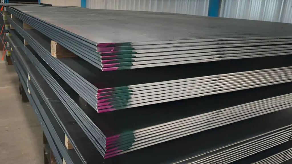
Sheet metal cutting is mostly done on a limited set of metals that are widely available in sheet form and commonly used in fabrication work. Each material behaves differently during cutting based on strength, hardness, and surface condition.
Common Sheet Metals
| Material | Properties | Cutting Behavior | Applications |
| Mild Steel | Strong, low-cost, easy to form | Cuts smoothly, slight burr formation, easy to process | Structural parts, frames, and general fabrication |
| Carbon Steel | Higher hardness than mild steel | Requires higher cutting force, faster tool wear | Machine parts, industrial components |
| Stainless Steel | Corrosion-resistant, work-hardened during cutting | Needs controlled speed and heat buildup during cutting | Kitchen equipment, medical tools, enclosures |
| Aluminum | Lightweight, soft, corrosion-resistant | Easy to cut, may stick to tools if speed is high | Aerospace panels, automotive parts, housings |
| Galvanized Steel | Zinc-coated for corrosion resistance | Coating affects edge quality and fumes during cutting | Outdoor structures, ducts, and fencing |
| Copper | Soft, highly conductive | Easy cutting, but it can deform if the pressure is high | Electrical parts, heat exchangers |
| Brass | Good machinability, smooth surface finish | Cuts cleanly with low tool wear | Decorative parts, fittings, plumbing components |
Industries Using Sheet Metal Cutting
Sheet metal cutting is used in a wide range of industries where structural components or assemblies are required for completed products. It can be applied to both mass production and custom fabrication applications.
Automotive Industry
Sheet metal cutting is primarily used in the automotive industry to produce body panels, vehicle components, and structural components. Examples include doors, body panels, brackets, frames, and chassis sections, which are typically created from steel or galvanised steel sheets before forming and assembling.
To meet the requirements of high-volume production, consistency and repeatability are key considerations during the cutting process. Following the cutting process, stamping or forming processes can be employed to achieve the final shape required for assembly lines.
Aerospace Industry
In aerospace applications, sheet metal cutting is used to produce components where both weight and accuracy are critical.
Examples include fuselage panels, wing structures, cabin interiors, and supporting brackets. Due to their strength-to-weight ratios, Aluminum and titanium sheets are commonly used in this sector.
Construction Industry
Throughout the construction industry, sheet metal cutting is widely used for building components such as roofing sheets, wall cladding panels, ventilation ducts, gutters & structural fittings.
The materials most frequently employed are steel and galvanised steel, which perform well in outdoor conditions. Most cutting within this sector is carried out using straight lines or simple shapes, with components subsequently installed on-site or assembled into larger systems.
Electrical and Electronic Manufacturing Industry
Within electrical and electronic manufacturing, sheet metal cutting is used to produce enclosures, control panels, chassis & mounting brackets that house electrical components.
Aluminium and mild steel sheets are typically selected for use within these applications. Laser cutting is commonly employed because it provides accurate openings and detailed cutouts needed for wiring, switches & component fitting without additional rework.
Heavy Equipment and Industrial Machinery
Sheet metal cutting in industrial machinery involves components of the machine body, protective covers, frame components, and structural supports. Parts of this nature are generally designed to carry a load and protect internal mechanisms.
The thickness of the steel being cut typically ranges from 0.0625″ to 0.500″, depending on design requirements. Most cutting processes employed by manufacturers of industrial machinery are either plasma cutting or heavy-duty shears. After cutting, most parts are then welded together with additional parts to form a complete machine structure.
What is the Easiest Way to Cut Sheet Metal?
The easiest method to cut sheet metal is with tin snips (or hand shears). They do not require setup and can be easily utilised for thin-gauge sheets.
Hand shears are primarily used for small fabrication projects, fit-ups, and repair. Hand shears are limited by the person operating them; however, they provide excellent results, cutting through thick and thin, and minimal curve cuthinner-gauge gauge metalmetals.
Common Tools Used for Sheet Metal Cutting
Depending on whether the project requires an accurate cut or if the operator prefers a quicker approach, a variety of hand tools and machine-based options are available for sheet metal cutting.
Manual cuts may be made quickly, utilising tin snips or hand shears. However, as the length of the cuts increases, the advantage of using power shears becomes apparent, enabling faster cutting with less physical labour.
Guillotines are used in shop or production settings that require clean, straight cuts from sheet stock. Nibbling is used when curved or angled surfaces are necessary. Since they use small incremental removal and greater profile control, they are more versatile than guillotines.
Angle grinders are widely used for quick cuts. In addition, angle grinders are often used during the repair/fabrication phase of a project. While they offer fast cutting capabilities, they lack precision.
For higher accuracy and/or complex designs, the user will typically select one of the following machine types: laser cutters, scroll saws, or electric metal saws.
These machine selections are high-accuracy measurements and dimensional requirements imposed on the finished product, rather than on the need for rapid fabrication.
Is Sheet Metal Cutting Expensive?
The primary cost factors associated with sheet metal cutting include:
Material type: Soft materials, such as aluminium, are easier to cut and therefore less expensive than harder materials, such as stainless steel or titanium.
Thickness: Thinner materials are generally less expensive to fabricate than thicker gauges.
Cutting method: Basic hand tools or shearing techniques are the lowest-cost option. Techniques that require more advanced equipment, such as laserjet cutting, result in lower costs due to improved edge quality/finish and increased dimensional accuracy.
Batch size: Smaller batches incur higher per-unit costs. Larger batch sizes have lower total costs due to improved repeatability. Deburring and edge-finishing operations also contribute to the overall cost of sheet metal fabrication.
Safety Practices in Sheet Metal Cutting
Sheet metal involves high-speed cutting and some exposure to heat or sparks. The key to accident prevention and maintaining control over your project is to follow all safety procedures.
Personal Protective Equipment (PPE)
You must put on PPE before beginning cutting work. Safety glasses will protect your eyes from flying metal pieces. Gloves will protect you from sharp edges by reducing the likelihood of cuts. Earplugs are required for noisy or vibrating equipment. Thermal cutting requires protective clothing to reduce exposure to sparks and heat.
Work Area Setup and Ventilation
When setting up your workspace for cutting, make sure there is good ventilation. This is especially true when using equipment that produces smoke or other particles. It is easier to see what you are doing if the air is clean. Your workspace needs to be free of clutter so that you do not slip or bump into something with your equipment.
Tool Condition and Maintenance
Your cutting tools need to be maintained and in proper working order. When your tools are sharp, they take much less force to operate, and you will have greater control over the quality of the cut.
If your tools become dull or damaged, the possibility of losing control increases. Inspect each of your tools before you start to cut and look for damage.
Securing the Material Before Cutting
Metal needs to be secured or clamped before cutting. If your metal is loose, it may shift abruptly, causing you to lose control of where your cut line ends up.
Secured metal will provide a solid cutting surface. The vibrations from most cutting equipment will also be greatly reduced by securing your metal.
Safe Handling of Cutting Tools
When using a power tool (e.g., grinder, saw, shear), it is best to operate it with controlled steadiness. If you are going to shut down your power tool while changing the part or for any other reason, do so before making any adjustments.
The grip on the tool as well as the po,e tool will help prevent loss of control during cutting processes, particularly in high-speed and/or heavy-duty operations.
Following Machine Instructions
Each power-cutting machine and tool has manufacturer-recommended operating procedures. When setting up and running your machines, follow these guidelines.
Proper operation extends the tool and reduces the risk of misuse. Do not exceed the rated capabilities of your tools.
Need Sheet Metal Cutting for Your Parts?
Sheet metal cutting is not just about making a shape. The optimal result depends on choosing the right process, setting correct parameters, and keeping the cut stable so the part fits later in assembly.
If you already have a design, the next step is usually deciding how it will actually be cut, laser, plasma, shearing, or waterjet, based on material and thickness.
At Prolean MFG, our sheet metal fabrication services are selected based on each part’s requirements, including material, thickness, and accuracy needs.
You can share your drawing or CAD file to get a quote for cutting, prototyping, or batch production.