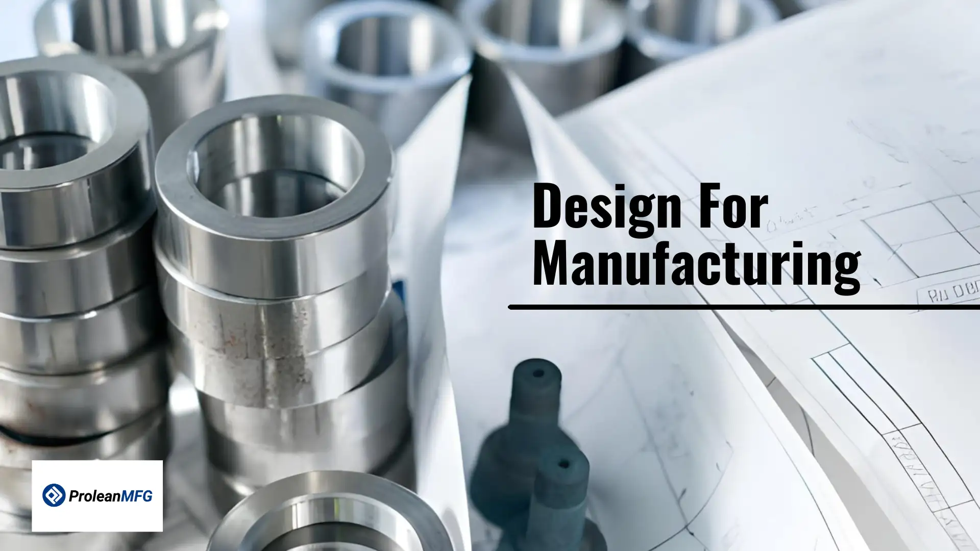

Product development or prototype manufacturing process does not end with a good concept. A design must also be practical to manufacture. Design for Manufacturing (DFM) is a structured approach to product design. It focuses on simplifying production without compromising performance.
Instead of optimizing only for function or aesthetics, DFM ensures that a part can be produced efficiently and at an affordable cost.
DFM is part of a broader engineering philosophy known as Design for Excellence (DFX). DFX includes several methodologies that improve various aspects of product development, including manufacturability, sheet metal design, assembly, reliability, serviceability, and cost control.
It is common to confuse Design for Manufacturing with Design for Assembly (DFA). While they are closely related, they address different challenges. DFM focuses on how individual parts are produced, while DFA focuses on how those parts are assembled efficiently.
In the following sections, we will explain what DFM means in practical terms, outline its core principles, and discuss how engineers can apply DFM analysis to reduce cost, simplify production, and improve product quality.
What Is DFM?
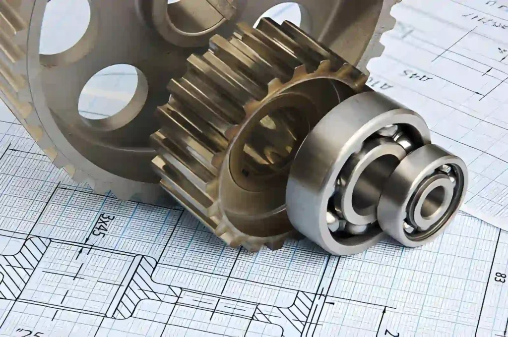
Mechanical Design Inspection
Design for Manufacturing, as an Engineering Process, establishes that a product will be produced at a reasonable price, effectively and consistently, and that the manufacturing process is aligned with the product’s design early in the design development phase.
Many products start as conceptual ideas that look good in theory but ultimately cannot be produced due to a range of manufacturing limitations, including available manufacturing processes, material selection, tolerance limits, geometric complexities, etc.
Manufacturing Design enables the identification of potential manufacturing limitations at the beginning of the product development process, ensuring the product can transition smoothly from prototypes to high-volume production.
The primary purpose of Design for Manufacturing is to provide a practical method to simplify product design. This may include using manufacturing-friendly materials, reducing complexity within individual parts, creating standardized components, or utilizing manufacturing processes that reduce production cycle times and required tooling.
It is essential to note that Design for Manufacturing does not aim to reduce product quality; instead, it seeks to eliminate unnecessary costs and risks associated with manufacturing.
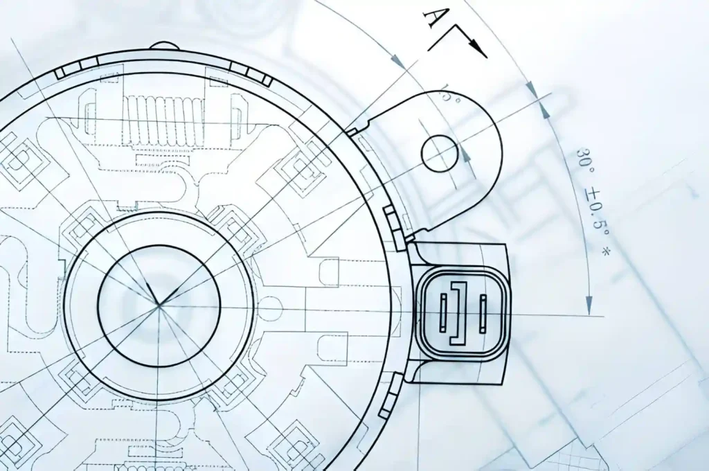
Tools technical drawing
In addition to providing a simplified design, Design for Manufacturing supports informed decisions on manufacturing engineering feasibility, manufacturing efficiency, cost control, and product scalability.
By analyzing the above-mentioned manufacturing considerations before production, manufacturers can eliminate costly redesigns, production delays, and quality issues that arise during the latter stages of the product development project.
With modern technologies such as digital simulation software and rapid prototyping, it is much easier to analyze and assess a product’s manufacturability during the initial design stages.
Engineers can now simulate the manufacturing process virtually, identify potential problems, and modify their designs before investing in tooling and scaling up to large production volumes.
Typical DFM Review Workflow
A standard DFM workflow helps ensure a product is easy to manufacture while meeting quality, cost, and time targets. The typical steps include:
- Concept Design Review: Evaluate initial designs for manufacturability and potential production challenges.
- Preliminary DFM Analysis: Analyze the design for material selection, tolerances, and process feasibility.
- Prototype Manufacturing: Create a prototype to test production methods and identify design issues.
- Design Revision Based on Manufacturing Feedback: Adjust the design according to insights from prototype testing and process feedback.
- Production Process Validation: Confirm that the final design can be efficiently produced at the required quality and volume
Objectives of Design for Manufacturing
DFM is used to ensure a product not only functions as intended but is also feasible to manufacture. The three key factors in any manufacturing project are cost, quality, and manufacturing efficiency.
Cost Reduction
The initial inquiry into the viability of any manufactured product is very simple: “Can we produce this product for a reasonable price?”
DFM will focus on where funds are being expended: materials, machining time, tooling, labor, energy, and scrap. Frequently, minor design changes reduce manufacturing cycle time and/or eliminate complex setup sequences. For example, eliminating excess tight tolerance(s) or excessive pocket depth may save significant machining time.
In other words, the objective is not to make the component inexpensive, but to eliminate any costs that add no additional value to the product.
Product Quality and Consistency
A design may appear flawless in CAD but still pose difficulties during fabrication. A design that includes features difficult to fabricate often results in variability, rework, or assembly issues.
DFM seeks to develop components that are easier to produce consistently. Examples of this include establishing standard hole diameters, limiting allowable tolerances, and/or modifying the component’s geometric characteristics to improve accessibility for manufacturing tools. Consistent production processes result in fewer defects and greater quality predictability.
Waste and Efficiency
Scrap, Rework, and extended cycle times all contribute to reduced manufacturing efficiency. DFM reviews the amount of material being scrapped, the frequency of setups required to complete an operation, and whether the operation itself could be simplified.
The elimination of waste is beneficial not only for the environment but also for lower production costs and improved production throughput. Design for manufacturing facilitates both sustainability and profitability.
Principles of Design for Manufacturing
Early in the Design for Manufacturing process, after the project’s objectives have been identified, the focus shifts to the practical elements that affect the production of the end product. Often this includes: manufacturing process selection; detailed design aspects; material specifications; working conditions; and regulatory compliance and standards.
Manufacturing Process
A significant focus during the initial stages of the Design for Manufacture process is determining whether the selected manufacturing process is appropriate and logical.
There are many methods to produce a given part. The housing of a system could be manufactured by machining, molding, or 3D printing; each method has its advantages and disadvantages with respect to tooling costs, production rates, surface finishes, and scale.
During the Design for Manufacture process, the designer compares the relevant attributes of each manufacturing method to the anticipated production volume and the desired functionality. Additionally, the designer assesses the details of the manufacturing processes to eliminate potential production issues (e.g., tool access in machining and draft angles in molding).
At times, the problem is not the manufacturing process itself, but rather the way it was planned. Inadequate tool orientation, excessive setup times, or overly aggressive cutting parameters can increase production costs and risks.
Mechanical Blueprint Design
Design Details
Often, designers initially develop designs that include features technically feasible but inefficient to produce.
During the Design for Manufacture process, engineers evaluate the design for manufacturing feasibility by looking at:
- Small internal radii require tools with matching diameters and longer machining times because internal corners can only be as sharp as the tool radius.
- Narrow deep pockets that cause tool deflection
- Unnecessarily tight tolerances that do not provide any added functional value increase manufacturing complexity and cost.
- Features that require multiple setups
In most cases, the design changes required to improve manufacturability are minor design modifications. Examples include increasing the internal radius of a feature to match the diameter of a standard tool, thereby reducing the time required to complete the machining operation.
Occasionally, a significant redesign of the product is required due to the fundamental difficulty associated with producing the design.
Material Selection
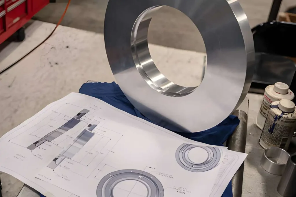
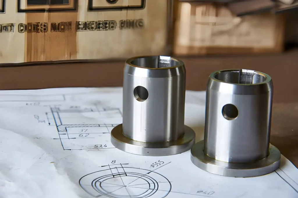
Stainless ring inspection
The choice of material affects the time required to perform machining operations, the rate of tool wear, the cost of producing the part, and ultimately the performance of the final product.
Occasionally, the reason for selecting a specific material is solely because of its strength, although there may be other options available that would meet the requirements of the application. Sometimes the chosen material is difficult to machine or costly to obtain.
During the Design for Manufacture process, the designer evaluates whether the material selected:
- Meets the performance requirements of the final product.
- It is readily available.
- It can be efficiently processed with the selected manufacturing process.
- Has the lowest total cost to produce the part.
Material selection involves finding the best compromise between the performance of the final product and the efficiency of the manufacturing process.
Operating Conditions
The operational environment where the part will be used is also essential. Mechanical stresses, thermal variations, moisture, or chemical exposures will all influence the engineer’s design decisions.
For example, if the part will experience significant mechanical stress, the wall thickness or reinforcement may be adjusted. Alternatively, if the part will be exposed to corrosive environments, material upgrades or coatings may be required.
During the Design for Manufacture process, the designer verifies that the design can withstand the intended operating conditions without requiring excessive manufacturing complexity.
Compliance and Standards
Many products are designed to comply with regulatory or industry standards. During the Design for Manufacture process, the designer verifies that the design and manufacturing strategy support these compliance requirements from the start.
Examples of compliance requirements that the designer will evaluate include the use of approved materials, the implementation of inspection protocols, and the inclusion of features that facilitate product testing.
Identifying compliance requirements early in the design process helps avoid manufacturing delays that may occur when they are discovered too late.
Design for Manufacturing vs. Design for Assembly
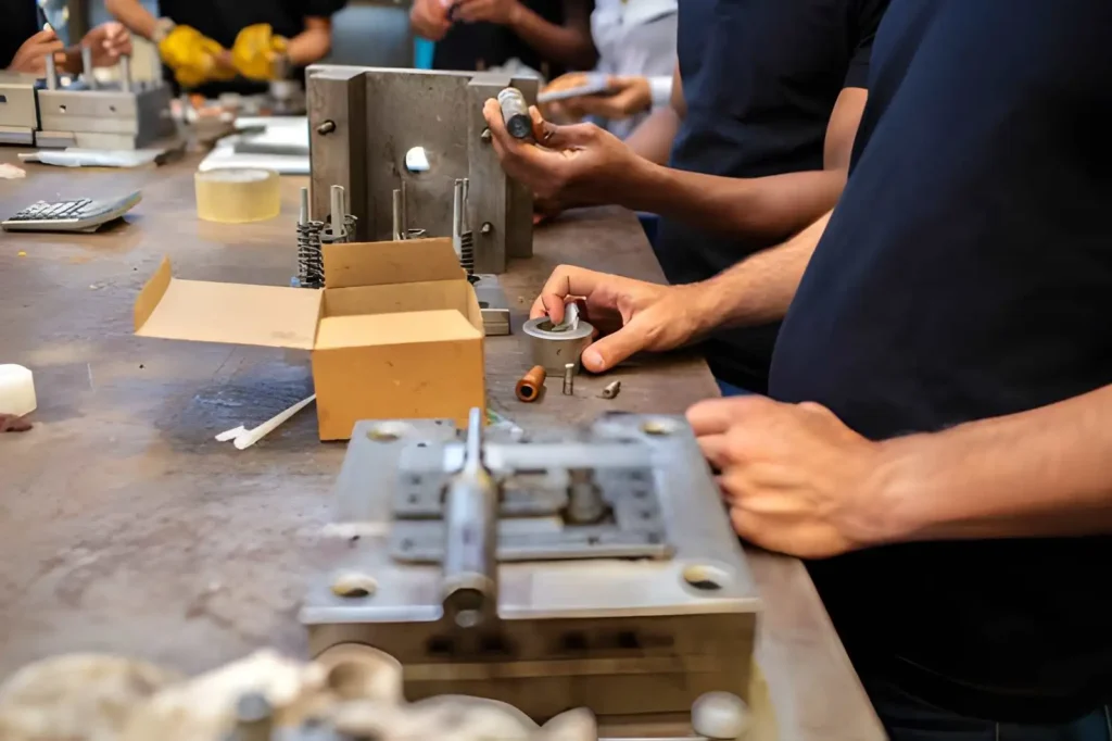
Press tool assembly
When DFM and DFA are used in the same project, there can be a significant overlap. However, when used individually, the two can be very confusing. Knowing the differences will help you avoid confusion throughout your product development.
Focus: Individual Parts vs. Complete Assemblies
Design for Manufacturing focuses primarily on individual components or parts. Therefore, DFM examines the geometry, material selection, tolerances, and capabilities of a specific process for a part. The purpose of DFM is to create an efficient and low-cost means of producing a part.
On the other hand, Design For Assembly focuses on how multiple components are assembled. DFA analyzes how components fit together, the number of components, the type of fasteners, how elements can be aligned, and the order in which components can be assembled.
The primary goal of DFA is to improve the efficiency of the assembly process by minimizing the time required to perform an assembly operation, reducing the complexity of the assembly, and reducing the likelihood of errors during assembly.
- In general, DFM asks: Is this part manufactured efficiently?
- DFA asks: Are these parts assembled efficiently?
Design Optimization vs. Assembly Efficiency
DFM focuses on optimizing the design of individual parts to improve their manufacturability using established processes. In doing so, DFM can address issues such as tolerancing, feature reduction, material selection, and process selection.
On the other hand, DFA is focused on optimizing the assembly process. DFA seeks to reduce the complexity of assemblies by limiting the number of parts, standardizing fastener types, adding self-locating features, and designing assemblies to minimize the need for specialized tools or precision alignment during assembly.
While DFM and DFA are distinct methodologies, they are often used together within the same project. While a part that is easily manufactured but difficult to assemble would still be considered inefficient, the two methodologies are often used simultaneously to achieve a balanced relationship between the manufacturability of individual parts and the efficiency of the overall assembly process.
Applying DFM Across Different Manufacturing Processes
Design for Manufacturing (DFM) is not applied equally across all processes. The DFM evaluation process will be affected differently depending on the manufacturing methodology. Each process has its own set of limitations, cost drivers, and potential failure risks.
Before the design is released to the shop floor, an adequate DFM review assesses how the design compares with the expected performance and limitations of the production process.
CNC Machining
Machined Parts on Drawing
Design for Manufacturing in CNC machining will focus primarily on:
- Tool accessibility
- Machine rigidity
- Overall machining time
Internal designs with perfectly sharp edges are typically difficult to machine, as they do not allow the use of commonly available cutting tools. Sharp internal corners require smaller-diameter tools, which reduce tool rigidity and increase machining time.
Using rounded-edge designs that match the most commonly available cutting tools can significantly improve machining efficiency.
Tool stability is another primary concern when designing machining features. Deep, narrow pockets or thin, tall walls reduce workpiece stiffness, leading to excessive vibration during machining.
This excessive vibration leads to poor surface finishes and poor dimensional control. Designing features to improve the width-to-depth ratio, or selecting alternative machining strategies, can eliminate these problems.
Additionally, the tolerance levels of features machined are an additional area where DFM can have a significant impact. While it is acceptable to maintain very low tolerance limits on functional features, applying them to non-functional features will require additional machining passes and longer inspection times.
Additive Manufacturing (3D Printing)
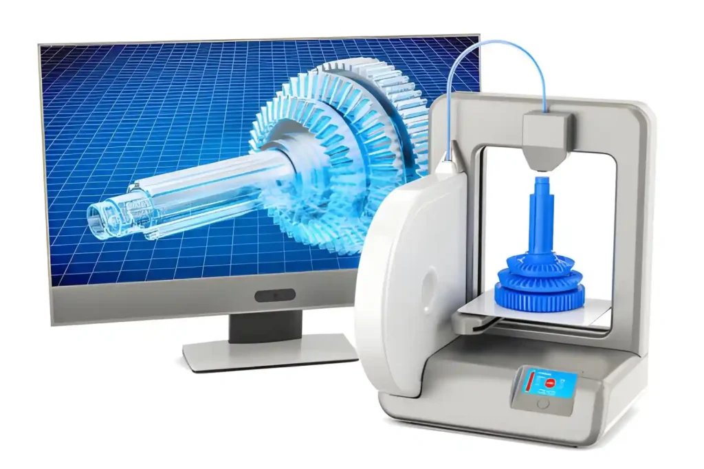
3D Printing Setup
When performing design-for-manufacturing evaluations for additive processes, the primary focus areas are print stability and the physical properties of the materials used during layer formation.
Overhanging sections of a design that lack support during printing can be distorted or collapse, depending on the additive technology used. Rather than simply providing additional support structures, DFM may recommend modifying the design geometry to include self-supporting features.
Additionally, design for manufacturability considers the minimum wall thickness that the printer can produce. Fragile sections may not bond correctly between layers. This often results in reduced part strength. By adjusting the wall thickness to match the printer’s nozzle diameter or layer resolution, the structural integrity of the final product can be significantly improved.
Thus, a key consideration in design for manufacturability in additive manufacturing is balancing material consumption with structural integrity and post-processing requirements.
Injection Molding
In injection molding, the focus areas of design for manufacturability are primarily tool design, material flow through the tool, and part removal from the tool.
Consistent wall thickness throughout the design is critical to avoid warping and sink marks. Changes in wall thickness can cause uneven cooling rates within the plastic section of the design, leading to warpage.
In many cases, design for manufacturability suggests gradual transitions or ribbed sections rather than large, solid sections of varying thickness.
The orientation of features relative to one another is also a critical component of design for manufacturability. Specific geometries may limit the direction of mold opening and, therefore, may require costly, complex tooling mechanisms.
By simplifying the design’s geometrical features, the cost of tooling and required maintenance can be reduced.
Finally, the amount of draft angle provided in the design can be critical to ensuring the successful removal of the molded part from the tool. If the draft angle is insufficient, the part may become stuck in the mold, resulting in defects and/or delayed production.
Making a minor design modification early in the design development phase can minimize potential long-term production issues.
Get DFM Support for Your Project at Prolean MFG
Effective DFM requires collaboration between design, engineering, and production teams. When these groups work together early, potential manufacturing challenges are identified before they become costly delays. This coordination improves part feasibility, shortens development time, and reduces production risk.
At Prolean MFG, every project undergoes a structured manufacturability review before production begins. We evaluate geometry, material selection, tolerances, and process suitability to ensure the design aligns with real manufacturing conditions.
Our team provides vacuum casting, additive manufacturing, and CNC machining services. The objective is simple: produce functional prototypes and production parts in a way that is technically sound, cost-controlled, and scalable.
If you have a design ready for review, our engineering team can assess its manufacturability and provide practical recommendations before you move into production.