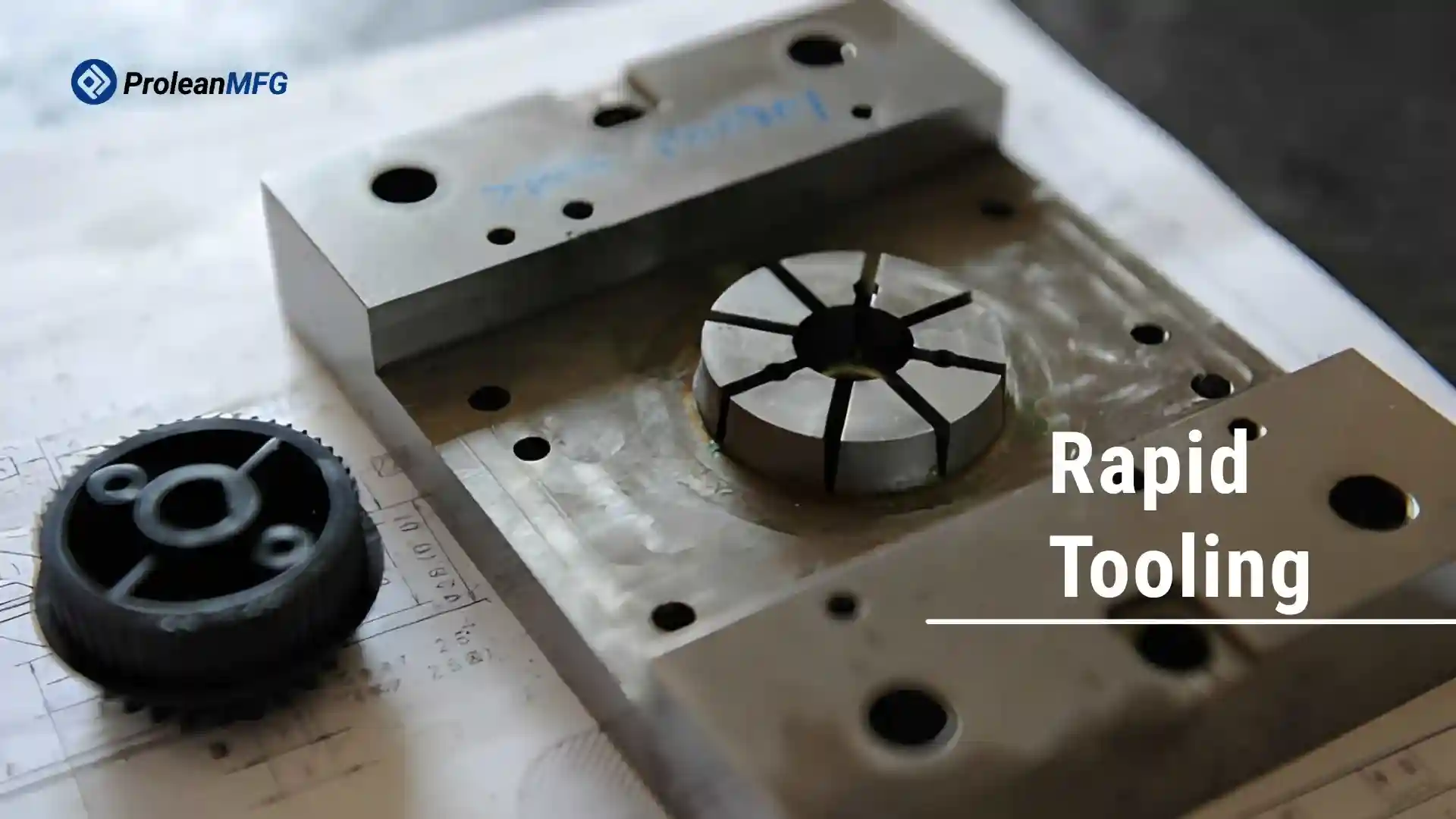

Tooling is often the longest lead item in prototype manufacturing. Injection molds, casting patterns, or forming dies can take several weeks to build, and the upfront cost is high before any parts are made. This slows down design validation and makes changes expensive.
Rapid tooling reduces this delay by using 3D printing and CNC machining to produce tools much faster. A basic mold or pattern can be ready in a few hours rather than a few days or weeks. In many cases, initial tooling costs drop by 40-60%, depending on size and part complexity.
In production, tooling is used to test parts before committing to full-scale tooling. It helps check fit, function, and material behavior under real conditions. Changes can be made early without restarting the entire tooling process.
This article explains how the rapid tooling process works, when it makes sense to use it, and what limits to consider before moving to production.
What is Rapid Tooling
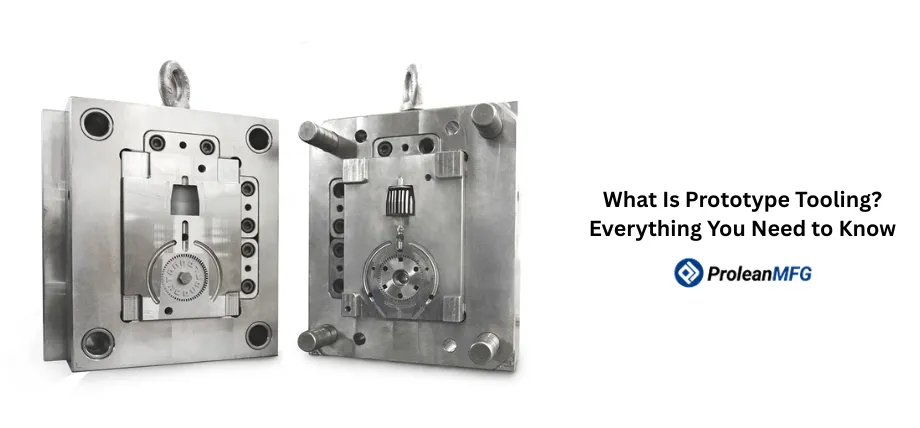
Rapid tooling is a technique that enables the production of molds, dies, and/or tooling inserts, allowing designers to test products or produce low-volume parts (small batches).
In contrast to traditional hard steel tooling, rapid tooling enables a functional tool to be created within a matter of days through additive manufacturing (such as 3D printing) or fast CNC machining.
As opposed to large-scale applications, where high-quality steel tooling has been developed for mass production, it requires longer lead times and larger initial investments. As such, it limits early product development.
Once an engineering change is initiated during this phase, the cost of modifying or replacing the existing tool(s) becomes exponentially higher due to the additional costs of modifying and/or rebuilding the original tool(s).
The utilization of rapid tooling avoids these delays. It facilitates engineers in creating prototypes using actual manufacturing processes (e.g., injection molding or casting), allowing them to verify part-to-part fit, material performance characteristics, and common issues such as shrinkage or warpage before creating final production tooling.
Typically, rapid tools are used for small-quantity requirements, from one piece to several thousand units, depending on the material selection and manufacturing process. Additionally, they can be utilized for quick delivery needs while awaiting completion of the final production tooling.
How Rapid Tooling Works
Rapid tooling is faster from design to production than “conventional” (or more accurately “traditional”) tooling. The primary goal is to produce a working prototype/tool so you can test parts or make limited quantities as soon as possible.
From Part Design to Tool Geometry
You begin with a three-dimensional computer-aided drafting (CAD) drawing of your part. This is the point at which you add the fundamental characteristics of the tool you will build (i.e., draft angle, part line, ejectors, etc.).
Most of these attributes apply to the manufacturing process for your parts (e.g., molding, casting). Now that your part has been designed, it needs to be made into a physical prototype. If using additive technologies, your tool is built up layer by layer.
Using subtractive technologies (such as CNC), the tool is machined from a stock material (aluminum or pre-hardened steel) to minimize time.
Tool Making and Finishing Work
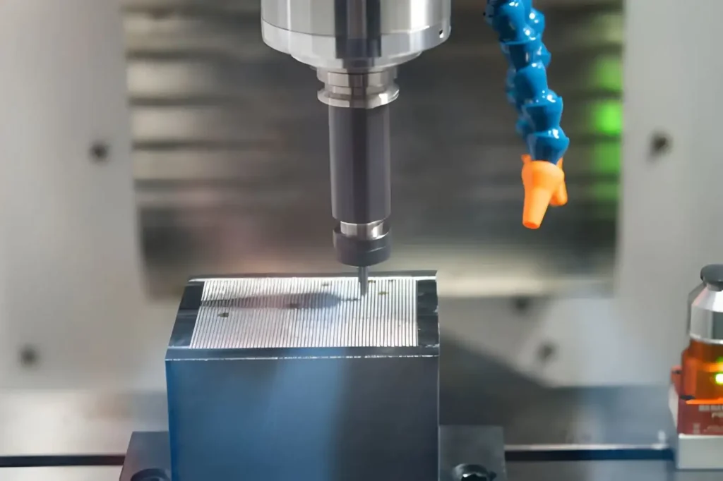
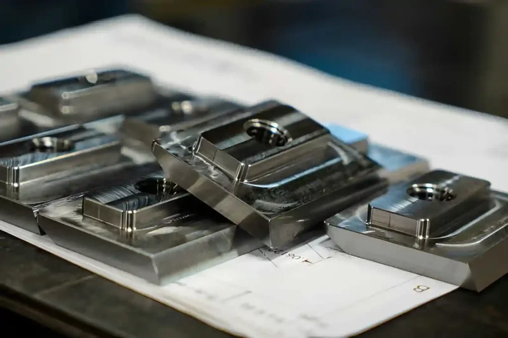
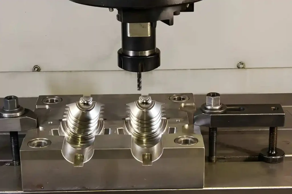
CNC machining mold cutting
Once you have created your tool, you will likely need additional finishing. Tools printed using additive technologies may require removal of support material and/or surface cleaning. Tools machined using subtractive technologies may require minor surface finishing to improve accuracy.
Depending upon the application, the area(s) of concern (edges/cavities) may be refined further, or inserts may be added to enhance the longevity of your tool. While all of these operations take time away from your overall objective, they are sufficient to allow you to use your tool to produce parts functionally.
Running Parts with the Tool
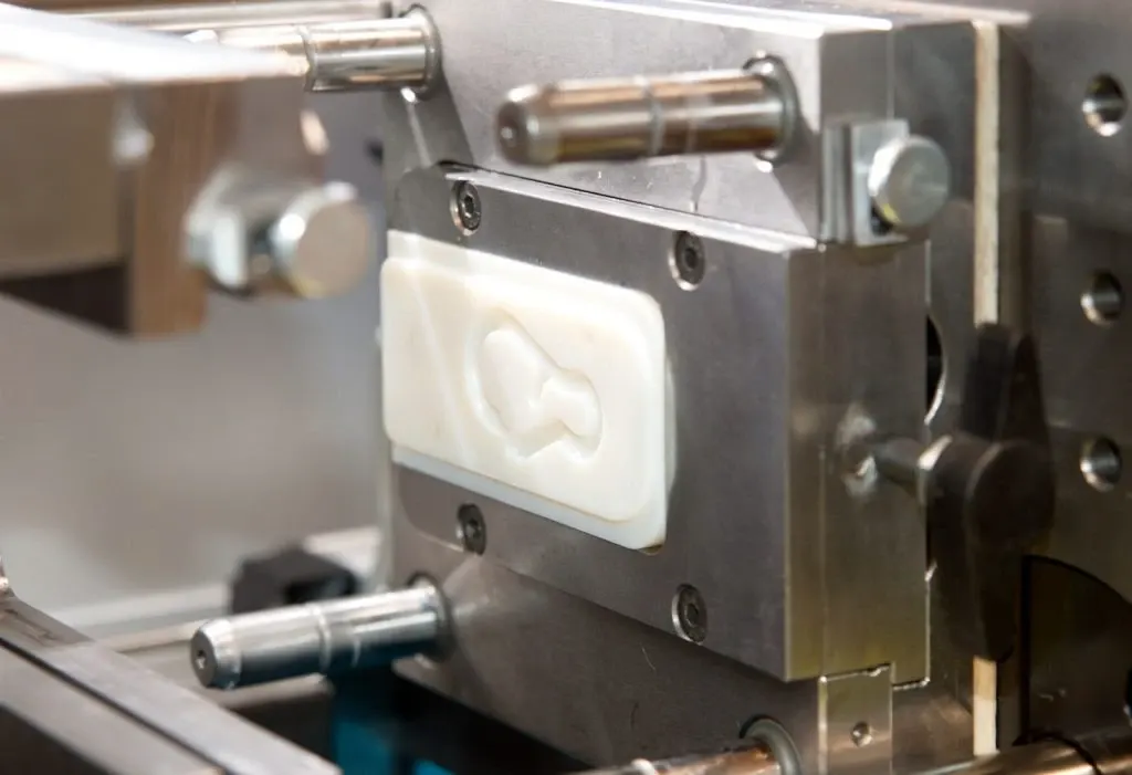
Tooling for glass bottle injection
Once your tool is complete, install it in standard equipment (e.g., injection mold machines, casting machines) and run parts under actual manufacturing conditions. This is where rapid tooling delivers the greatest value.
You will have the opportunity to evaluate how your part functions in an actual manufacturing environment, specifically how material flow occurs during molding and cooling, and whether defects occur (shrinkage/warping), etc.
The number of parts your tool can produce before wear-out depends on the material used and the manufacturing method. Typically, rapid tooling applications result in less than 1,000 cycles (or runs).
Materials and Methods Used
Rapid tooling utilizes materials that are quicker to process than those traditionally used for hardening (steel). Aluminum is commonly used because it can be quickly machined.
When greater strength is required, pre-hardened steel alloys are used. Additive techniques employ high-temperature resin systems and metal powders. Depending on your specific requirements, different manufacturing methods can be employed.
For example, additive manufacturing can provide rapid turnaround of complex geometries. Subtractive manufacturing (CNC) typically provides a superior surface finish and better dimensional accuracy. Often, a combination of additive/subtractive methods is used to achieve optimal results in terms of speed and precision.
What Is the Difference Between Rapid Tooling and Rapid Prototyping
While both occur during the same phase of product development, their uses are distinct when creating your product.
Rapid Prototyping – Checking Design Shape and Fit (Early Stage)
Metal prototypes
Rapid prototyping involves making components directly from computer-aided design (CAD) data through additive fabrication processes, typically referred to as “printing.” Since speed is emphasized over detailed quality, the initial evaluation focuses on checking the part’s shape and whether it fits together as planned.
With the ability to produce parts in hours (or even minutes), rapid prototyping is ideal for iterative design changes. Unfortunately, the resulting parts are generally fabricated with materials that don’t accurately replicate production-grade material properties.
As a direct consequence, although prototypes accurately represent the part’s visual characteristics and layout, they cannot necessarily be relied upon to provide a true indication of mechanical performance under long-term use or process-related behaviors.
Rapid Tooling – Testing Production Methods & Materials (Later Stage)
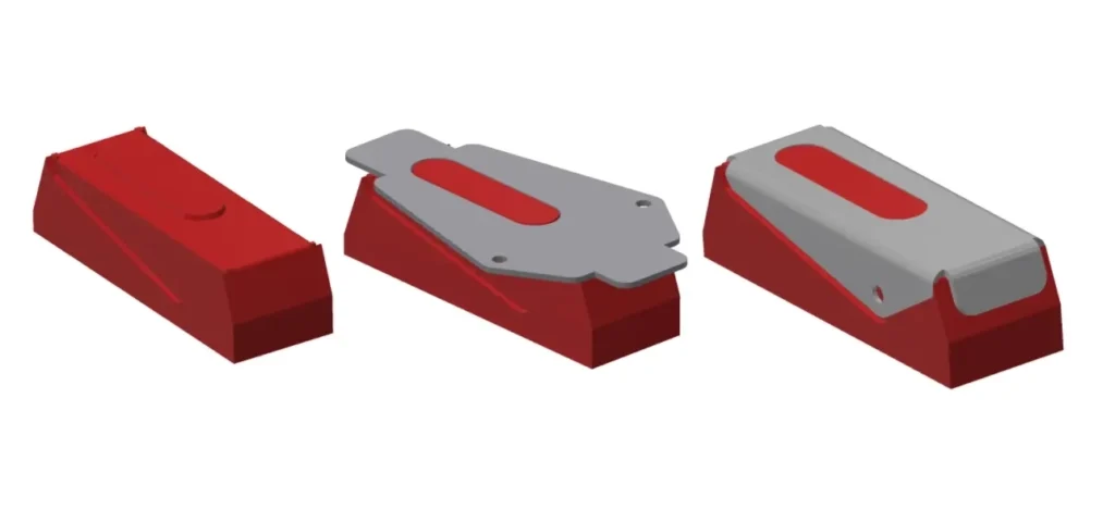
Unlike rapid prototyping, which produces parts directly, rapid tooling creates molds, dies, or patterns used to make production parts, using various manufacturing methods, including injection molding or casting.
By allowing parts to be manufactured with the exact materials and production methodologies used during manufacturing, designers/engineers can assess real-world factors such as material flow, shrinkage, surface finishes, and structural integrity.
Additionally, designers/engineers can determine whether production issues will arise before building large-scale tooling.
Functional Differences in Use
While both rapid prototyping and rapid tooling fall into the development stage of product creation, their primary applications differ.
Rapid prototyping primarily uses design geometries to verify and iterate until satisfactory design configurations are developed rapidly. Rapid tooling follows this and verifies that production procedures will function properly once production begins.
Simply put, rapid prototyping verifies your design configuration. Rapid tooling verifies the production procedure associated with your design configuration.
Both technologies are typically utilized in conjunction. Once a designer has iteratively created multiple design configurations through rapid prototyping, they transition to rapid tooling for final validation of the part being produced, before developing full-production tooling.
What Is the Difference Between Soft Tooling vs Hard Tooling
When you need a specific number of items (volume), and you know how many will fit into one run (tolerance), choose the option that gives you the best ability to reproduce your product consistently (process stability).
Soft Tooling for Low Volume and Early Validation
Soft tooling
Soft tooling is made using a mold created from a model of the final item. This mold is made from an inexpensive plastic called silicon. A mold is made from this model to cast Urethane parts. These molds are made using either a computer-controlled milling machine or 3D printing.
As previously stated, the lifetime of a soft tooling is relatively short. Depending on the part’s complexity and the type of urethane, the typical mold run is 20 to 100 pieces.
Because the dimensions of soft toolings vary from piece to piece, the finished part’s accuracy is unreliable. Due to this variability, soft toolings are only suitable for initial visual inspections and for checking whether certain features work. As more pieces are produced, these differences become even larger.
Since soft tooling is relatively inexpensive and takes very little time to create and test, it is ideal for low-cost applications and for testing a new concept before investing in creating expensive, precise tooling.
However, because soft tooling does not accurately simulate the actual manufacturing process (like injection molding), you can’t accurately assess how the actual manufactured product will behave. In addition, since soft tooling has no “insides” (like injection molding), you can’t see internal defects.
Hard Tooling for Process Stability and Higher Volumes
Hard tooling
Hard tooling refers to the creation of molds using metals. Most aluminum molds can produce tens of thousands of parts. Hardened steel molds can produce hundreds of thousands of parts.
Aluminum tooling generally lasts anywhere from a few hundred parts to about 40,000 parts before needing replacement. When designing aluminum parts, designers should aim to minimize complex geometries and avoid introducing stress concentrations.
Steel molds last longer than their aluminum counterparts. With proper care, steel molds can support large volumes with minimal variation among individual parts.
Unlike soft tooling, hard tooling provides consistent environmental factors during processing. Hard tooling replicates all aspects of commercial injection molding. Processing conditions include: uniform cooling rates, identical shrinkage characteristics, and consistent surface finishes.
Selection Based on Production Requirements
Soft tooling is used for low-volume production, to validate designs before moving to production, and for products where cost is a major factor. For example, if you don’t plan to manufacture many units of a particular product, it may be cheaper to start with soft tooling until you determine how well the product performs after a few samples are built.
Hard tooling is chosen when high volumes are anticipated, and consistency is needed. Once you’re ready to start mass-producing your product, you can do so repeatedly with hard tooling.
Rapid Tooling Techniques Used in Manufacturing (Direct Vs Indirect)
The main differences among the various types of rapid tooling relate to how the tool is manufactured, its service life, and the level of production loads it can support.
Selection of the appropriate rapid tooling method will depend on a combination of factors, including cycle count, heat exposure, and required geometric stability (i.e., dimensional integrity). While these elements do relate to production rate, they cannot be determined solely by production rate.
Direct Tooling Methods
Additively Manufactured Tool Inserts
3D printed dies for tooling
3D printing (additively manufactured) tooling enables the direct creation of mold inserts or complete cavities from computer-aided design (CAD) data, using technologies such as stereolithography, multi-jet fusion, and binder jetting.
Stereo Lithography (SLA) resins are frequently used to produce tooling inserts for low-pressure or small-run injection-molded parts.
This class of tooling generally supports 50 to 1000 injection cycles per tool insert, depending on the resin quality and wall thickness. While high-temperature resins can withstand relatively brief exposures to 200°C to 240°C, continued thermal cycling adversely affects dimensional accuracy.
Binder-jetted or laser-sintered metal inserts provide greater rigidity than those produced with SLA resins. Moreover, these inserts require additional processing steps, such as sintering and/or machining; however, the resulting tooling has mechanical properties approaching those of aluminum tooling and can therefore support higher-volume production runs.
This type of tooling is selected when there is an urgent need to complete the tool quickly and when design revisions are anticipated before “freezing” the final geometry.
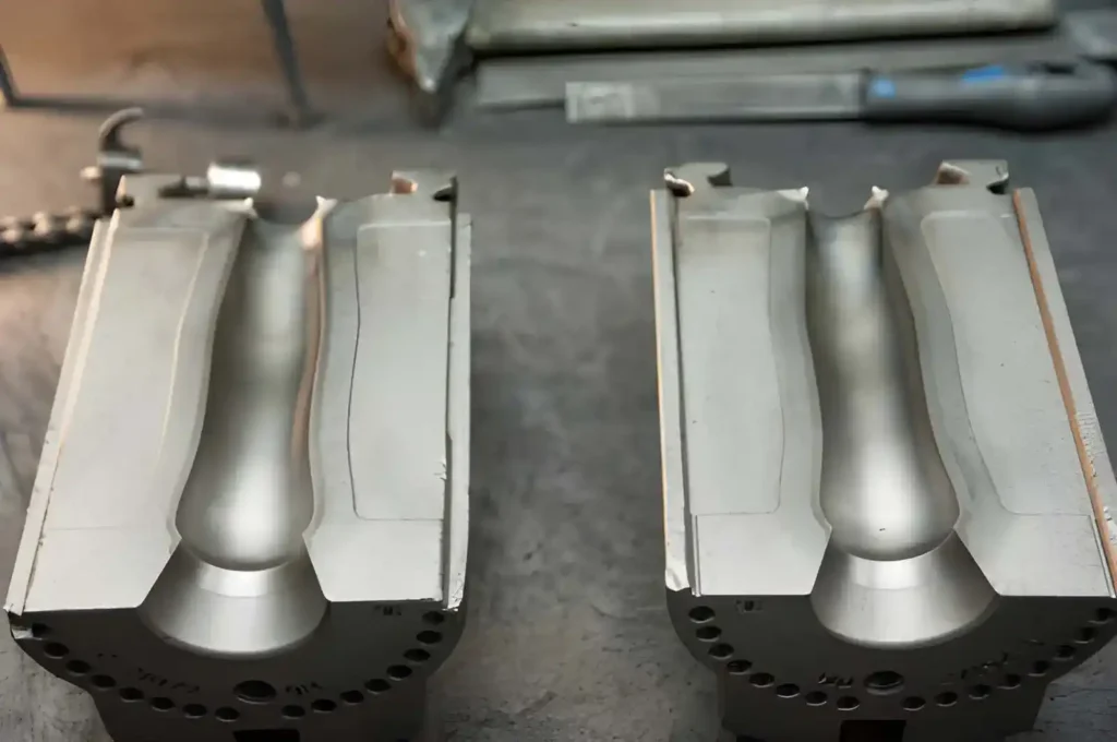
CNC Machined Rapid Tooling
CNC rapid tooling
Computer-controlled machines are used to create tooling from blocks of aluminum or pre-hardened steel. Aluminum tooling is the most commonly employed material for rapid injection-molded parts.
Aluminum can be machined 5 to 10 times faster than tool steel and typically provides a maximum usable injection cycle count of 2000 to 50,000, depending on the specific characteristics of the molded part, the resin used, and cooling conditions.
The surface finish of aluminum tooling obtained through machining is directly related to the specific toolpath strategies employed.
In general, machined aluminum molds achieve average surface roughness (Ra) values of approximately 0.8 to 1.6 microns without subsequent polishing. Surface finishes in this range are adequate for the majority of prototype and bridge production parts.
Machining-based rapid tooling is typically selected when dimensional stability, repeatability, and control are more important than actual total tool life.
Silicone-Based Casting Tools
Flexible molds can be created using a variety of different materials, including silicone rubber. A typical procedure involves first creating a master pattern, which can be produced using stereolithography (SLA) or computer-aided numerical control (CNC) machining.
Once the master pattern has been created, a liquid silicone material is cast into the voids within the master.
Flexible molds are primarily used for urethane casting applications. Flexible molds provide an estimated number of usable casts ranging from twenty to one hundred before significant degradation of dimensional accuracy begins to occur.
Dimensional variability associated with shrinkage is also significantly greater than that observed with rigid tooling systems; therefore, dimensional variations of ±0.2% to ±0.5% can be anticipated, depending on the casting material used.
Flexible molds are typically employed when rapid evaluation of the molded part’s geometry is necessary; however, the cost justification for developing an injection-molded tool is required.
Reaction Injection and Urethane Mold Systems
Polymer reaction injection molding employs lower-pressure chemical curing rather than thermoplastic melt processing. As a result, rapid tooling for PRIM is typically fabricated from aluminum or reinforced resins.
Since injection pressures remain relatively low during PRIM, the stresses generated in the mold are correspondingly reduced, enabling simple mold designs without extensive cooling channel configurations.
Typical batch sizes for PRIM range from 100 to 5,000, depending on the polymer chemistry and the thickness of the molded part’s walls. Mix ratio control and wall uniformity are typically considered more critical than mold wear in PRIM applications.
Electroformed Nickel Tooling
Electroforming produces a thin layer of electro-deposited nickel onto a master pattern. Following the removal of the original master pattern, a metal cavity with an extremely accurate reproduction of the master’s surfaces remains.
Due to their ability to accurately reproduce fine details on the surfaces of molded parts, electro-formed nickel tooling is frequently used in applications requiring high surface fidelity, including optical components and other precision plastic items.
Although longer build times may be required to increase plating thicknesses (typically 0.5mm to 6mm), surface roughness values as low as Ra = 0.4 microns have been reported.
Indirect Tooling Methods
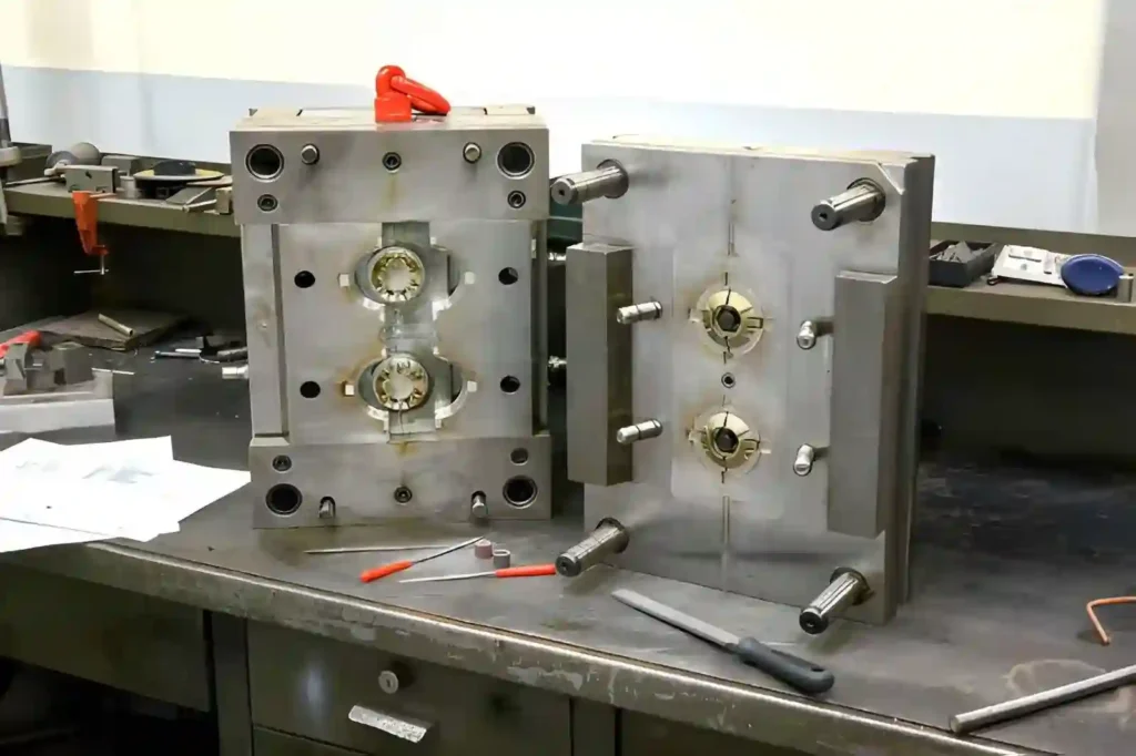
Rapid Injection Molding Tools
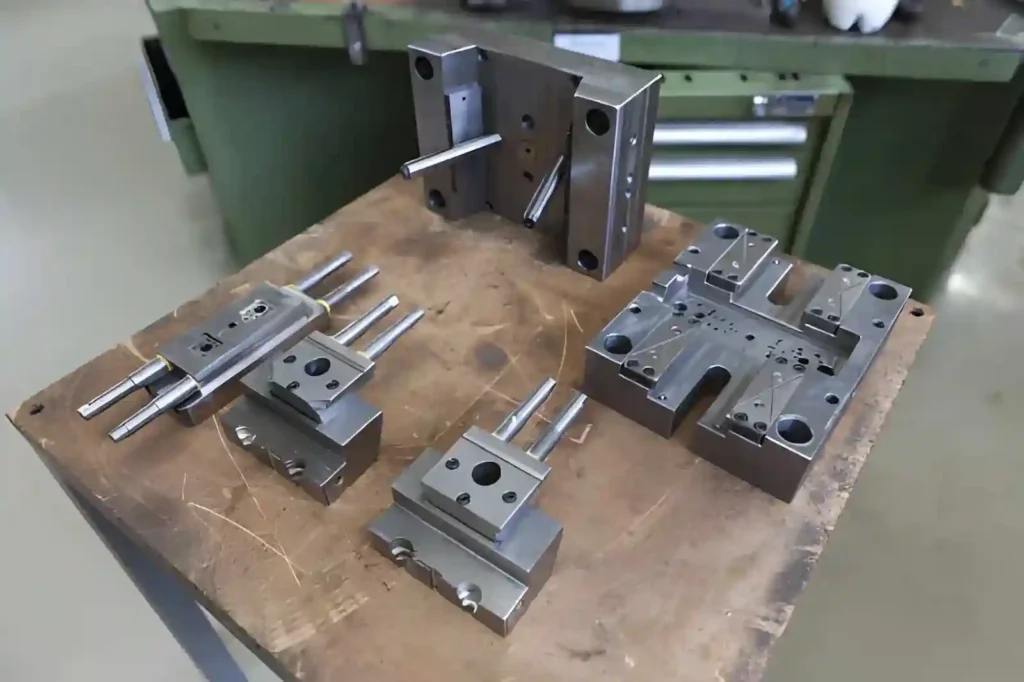
Metal tool for molding
Tooling for rapid injection molds is produced using either aluminum machining or additive inserts to facilitate quick product development. Aluminum molds are generally employed for bridge tooling production. These molds will last through approximately 500 to 10,000 cycles.
Additionally, they provide approximately 20% to 40% faster cooling rates (as opposed to Steel) because of their increased thermal conductivity.
Printed molds can be used for low-pressure resins; however, most are used to validate flow behavior, gate placement, and shrinkage predictions rather than for actual production.
This method offers the advantage of testing processes before producing hardened steel tooling under similar production conditions.
Thermoforming Tooling Systems
Thermoforming molds are generally created by machining aluminum or printing with high-temperature polymers.
Part clarity and finish can be greatly affected by how well the mold surface is finished, since the thermoformed plastic sheet forms to the mold surface. The placement of vents in the mold is critical to prevent air entrapment during forming, particularly when creating deep-draw geometries.
Printed molds are typically used to validate designs quickly, while aluminum molds are used for the final production run where consistent part dimensions are necessary throughout each cycle.
Compression Molding Tools
Compression tooling is used for rubber, silicone, and composite materials. Printed resin or soft metals are commonly used for rapid tooling in compression molding applications.
Since the pressures in compression molding are lower than those in injection molding, there is less stress on the tooling.
However, thermal expansion is a major concern when achieving accurate part dimensions. Cycle times may be longer; however, the costs associated with creating the tooling are significantly lower, making it feasible to produce gaskets, seals, and test parts from composites.
Casting-Based Rapid Tooling
Workflows based upon casting utilize printed or machined patterns to produce metal or polymer parts.
In investment casting, printed patterns have replaced wax models, reducing the amount of time spent preparing the pattern from days to hours. It is recommended that shrink compensation be included in your CAD file, typically ranging from 1% to 2%, depending on the alloy type.
Patterns for sand casting can be printed directly, enabling complex internal features without assembling manual cores. While accuracy has been lost relative to machined tooling, the reduction in setup costs is significant.
Sheet Metal Forming Dies
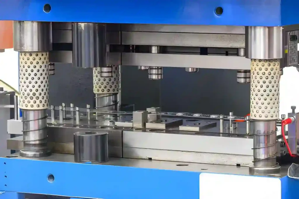
Sheet metal stamping dies
Rapidly developed dies for sheet metal forming are available in either printed polymer or machined aluminum for low-to-medium force forming operations.
Printed dies are typically utilized for validating designs; however, their durability limits them to relatively few forming cycles after which they begin to affect die geometry.
Aluminum dies are used when you require consistency in your formed parts across numerous forming runs.
Regardless of whether you use printed or machined dies, springback characteristics remain largely dependent on the material being formed. Therefore, you should perform some level of process development to establish acceptable operating parameters.
Advantages and Disadvantages of Rapid Tooling
Rapid tooling reduces the time to develop your product and lets you see what will happen during production before investing in production tooling. The biggest benefit of using rapid tooling is for small to medium quantities (low to medium volume), since cost and speed typically outweigh the tool’s lifespan.
Advantages of Rapid Tooling
Faster tool delivery and lower initial cost
Tooling developed through rapid prototyping can be developed much faster than with traditional methods. Inserts printed via 3D printing technologies can be completed in 24 hours or less; aluminum tools made on a computer-controlled milling machine can be completed in 48-72 hours, depending on their complexity.
Typically, the up-front cost of rapid tooling is lower than that of steel tooling due to the absence of a lengthy heat-treating process and/or extensive finishing. Frequently, the up-front tooling cost can decrease by 30% to 70%.
Early testing with real production materials
Functional prototype parts can be created using production resins/alloys, which provides an opportunity to observe material properties such as shrinkage, flow behavior, and warp directly rather than solely relying on simulation results. Additionally, the ability to run actual production tests will enable users to establish process parameters, such as injection pressure, mold temperature, and cycle time, before final production tooling is completed.
Useful for low volume and design changes
Rapid prototyping enables the production of small quantities of prototype parts and design revisions without rebuilding full tooling. Localized changes to insert-based molds, such as gate placement or geometric modifications, can be easily made.
Additionally, rapid prototyping is beneficial for companies that need to create numerous versions of their design(s) before establishing the final version for mass production.
Sufficient accuracy for bridge production
Insert-based molds and aluminum tooling provide sufficient accuracy for most functional prototype parts. Typically, the achieved accuracy is acceptable for engineering validation and pre-production testing. Provided proper controls are in place within your processes, you should see repeatable accuracy even during limited production runs until you switch to hardened-steel tooling.
Cost efficiency at limited volumes
In terms of cost-effectiveness, rapid prototyping is most effective for 50 to 5,000 units. Within this range, it keeps costs associated with developing steel tooling down while still allowing the creation of functional parts for testing/limited releases.
Disadvantages of Rapid Tooling
Limited tool life
Molds constructed from soft materials (such as silicone) and printed inserts have shorter lifespans than hard-metal tooling.
While silicone molds may last only dozens of cycles, aluminum tools are generally limited to tens of thousands or hundreds of thousands of cycles, depending upon the design. The first signs of wear appear in high-stress areas, such as gates and sharp corners.
As unit volume increases, the price-per-part cost decreases relative to hardened-steel tooling. As machine time increases alongside manual labor, rapid prototyping does not scale efficiently to large-scale production.
Less Thermal Dimensional Stability
All non-hardened steel tooling is more sensitive to heat and repetitive use. Over time, both can result in gradual dimensional changes/surface changes. Printed or silicone tooling performs particularly poorly under high-temperature/high-pressure operating conditions.
Variation between tools and processes
Most rapid prototyping processes involve a series of steps, including printing, machining/fabricating, and assembly.
At each stage, some variation in surface finish and dimensional accuracy occurs. As such, additional inspection is required compared to typical production tooling.
When Not to Use Rapid Tooling
The benefits of rapid tooling are most pronounced in validating designs and producing small to moderate volumes of products (up to 50,000 units per year). When a product’s volume exceeds what can be produced within the process limitations of rapid tooling or the physical limitations of the materials used, it is no longer an efficient method for producing the product.
High Volume Production Beyond 50,000 Parts Per Year
When annual volume exceeds about 50,000 units or cycle times drop below about 20 s, rapid tooling becomes less productive.
At these volumes, automated steel tooling systems have a much lower cost per unit, improved cycle-to-cycle consistency, and longer tool life.
Parts Requiring High Wear or Temperature Resistance
Due to thermal cycling stresses or exposure to abrasive resins, filled polymers, or other high-temperature plastics, soft tools and printed inserts will fail sooner than expected.
Early signs of failure include excessive wear on gates, edges, gears, and/or high-flow-rate areas, resulting in varying degrees of dimensional shift. In addition to the obvious problems associated with tool wear, soft tools will also exhibit inconsistent finishing capabilities throughout their production run.
Hardened steel tooling must be used to provide consistent production results during extended production runs with harsh materials.
Applications Requiring Premium Cosmetics
While printed and aluminum tooling methods can produce acceptable finishes initially, they will often deteriorate as production continues. This is especially true when subjected to repeated thermal cycles (cooling/heating) or if production runs continue for extended periods.
Steel tooling, when cooled slowly and consistently, produces superior cosmetics as compared to printed or aluminum tooling.
Applications of Rapid Tooling in Manufacturing
Rapid Tooling is primarily utilized for design validation (the first phase), process verification (the second phase), and short production Runs (the third phase).
Automotive Parts Development and Short Production Runs
Interior trim components, clips, brackets, housings, and early-stage exterior trial parts are typical examples of how automotive companies utilize rapid tooling. Interior Trim Components are evaluated to ensure proper fitment, correct assembly orientation, and appropriate material performance at end-use operating conditions.
Aluminum moldings are most frequently employed for short-run manufacturing. They provide approximately 2000 to 10,000 injection cycles, depending on mold temperature management and the specific resin being molded. In addition, Early Stage Trial Inserts are printed with the expectation of failure under 500 injection cycles due to excessive wear, which compromises accuracy.
Ford utilizes their own additive systems to manufacture fixtures and low-volume parts for line Testing and initial vehicle builds.
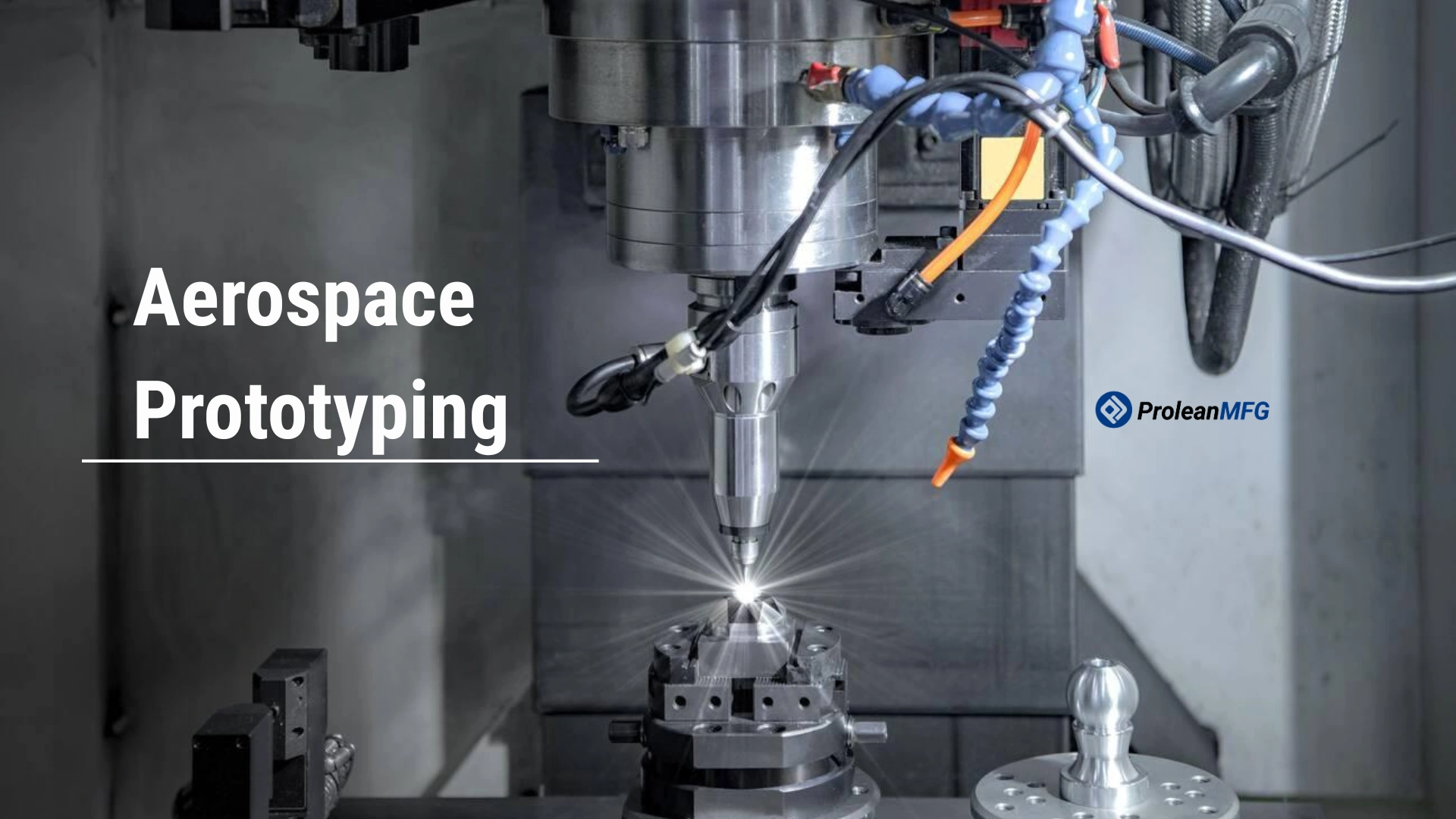
Aerospace Component Trials and Structural Checks
Companies in the Aerospace Industry use rapid tooling to evaluate Prototype Parts that will ultimately undergo final tooling approval. Examples include Airflow Parts, Internal ducts, and structural Components.
Resin Patterns created via Printing Methods are utilized for Investment Casting, while CNC Alumina Molds are employed for composite layups.
These molds allow manufacturers to test wall-thickness behavior, load response, and Shape Stability during the early stages of product testing. Manufacturers typically remain below 500 parts manufactured from the design before transitioning to Production Tooling.
Airbus has used cast prototypes to evaluate turbine blade shapes before deciding to proceed with final metal tooling.
Medical Device Testing and Limited Production
Companies that use rapid tooling for medical devices develop surgical instruments, device encasements, and patient-specific parts to conduct functional testing before obtaining regulatory approvals.
Silicone molds are used for Soft Components; typically supporting 50 to 300 cycles. While aluminum injection molds are used for harder plastics, they can support up to several thousand cycles, depending on part geometry and Material Properties.
Functionality Fit, Sealing Performance, and Handling are confirmed before preparing Production Molds using this method.
Electronics Housings and Enclosure Development
Plastic enclosures, connector bodies, and snap-fit Components are common components developed using aluminum molds or printed Inserts during product development.
Using these molds allows manufacturers to verify assembly fit, wall thickness balance, and stress points in snap-fit zones. Batch sizes range from 500 to 5,000 units, depending on the complexity of the product design. Reducing changes after final tooling is complete is an additional benefit.
Small Metal Parts are Made Through Casting Methods
Rapid tooling to create wax or resin patterns for investment casting small metal components is a viable option.
Jewelry, fittings, and precision metal shapes are examples of products successfully cast using this method. Creating Printed Patterns provides significant reductions in pattern preparation time over manual or machined wax models. Typically, batch sizes range from 10 to 500 units. Shrinkage allowances are incorporated into designs; generally, 1% to 2% shrinkage, depending upon alloy type.
Composite and Carbon Fiber Structures
CNC aluminum molds or printed masters are used for Carbon Fiber Lay-Ups and Laminated Structures for composite tooling. Drone frames, panels, and lightweight covers are examples of products developed using this method.
Aluminum Molds are often selected when high surface quality and dimensional control requirements exist throughout multiple cycles. Batch sizes for composite applications typically range from 20 to 500 units; beyond that, wear of the mold surface begins to affect finish quality.
Sheet Metal Forming and Low-force Stamping
Rapid tooling is also used for bending, forming, and light stamping, where full Production dies are not required. Printed polymer tools are used for initial geometric validation, while aluminum tools are used for short production run manufacturing.
Prolean MFG Rapid Tooling Support
Prolean MFG offers Rapid Tooling Services for prototype development, design validation, and low-volume production when standard tooling lead times are impractical.
We work with CNC-machined aluminum tooling and prototype injection mold inserts to produce parts in production-grade materials for early testing and short runs. This approach helps confirm fit, geometry, and process behavior before moving to hardened steel tooling.
Our team reviews part geometry, material selection, and expected cycle count to suggest a suitable tooling approach and a realistic lead time for the application.
If you have a design ready or need support in selecting a tooling method, you can contact Prolean MFG to discuss your project requirements, expected volume, and material needs.