
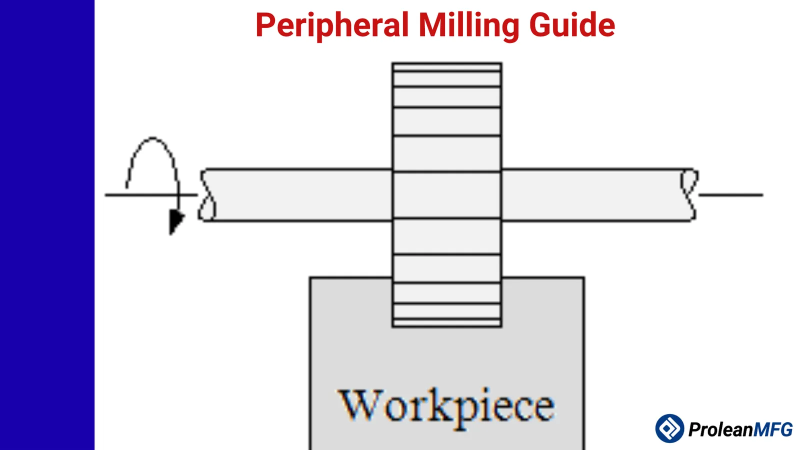

Peripheral milling is a common machining process that removes material using teeth on the outer diameter of a rotating cutter. The cutter axis is parallel to the surface being machined. The process produces grooves, profiles, slots, shoulders, and other features.
Process engineers constantly require or use this milling type, yet the details of its distinction, functions, and applications may not be well understood.
Peripheral milling can be identified by how the tool axis is oriented to the workpiece surface, the cutting parameters involved, design and machining strategies, and industrial applications, among other elements.
The design guidance and side-by-side comparison with face milling, along with fixes for common machining issues, serve to expound the process further.
Whether you are examining the relevance of your design or specifying a part, this article will provide the practical insights to get your peripheral milling project right the first time.
What is Peripheral Milling?
Peripheral milling uses the outer circumference of a special rotating cutter to produce shoulders, step features, grooves, slots, and profiles on a workpiece. The process can also be used for edge preparation.
The wall or surface being machined and the axis of the peripheral milling cutter are typically parallel. The edge of the peripheral milling tool has teeth, which remove material gradually for accurate results.
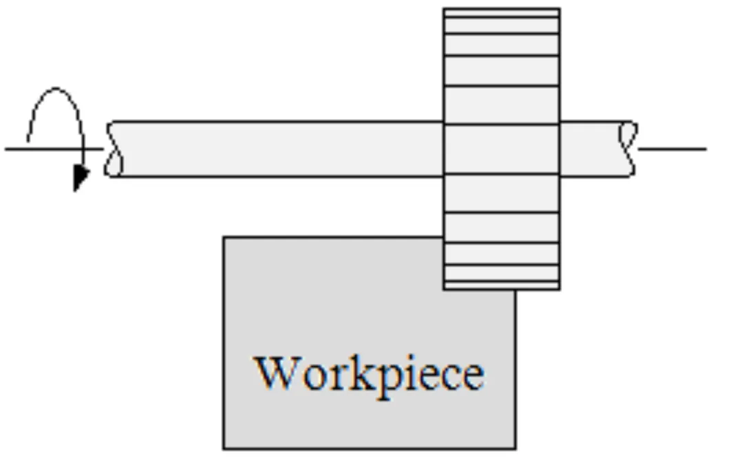
Peripheral milling
Peripheral milling is one of many milling processes performed on different materials for a wide range of industries. Collectively, these processes are cost-effective for prototyping and production. CNC milling can attain tight tolerances, but the final accuracy depends on geometry, setup, tooling, and machine capability.
The Peripheral Milling Process: Steps
Peripheral milling follows the usual CNC machining sequence of: Workholding and setup, toolpath execution, material removal, and post-process inspection.
Step 1: Workholding and Setup
The workpiece is set on the CNC machine and secured using clamps and vises. Firmness is critical to prevent tool breakage and maintain dimensional stability. The workpiece must withstand radial tool force and tangential cutting force.
Step 2: Toolpath Execution
The CNC machine spindle rotates the peripheral milling cutter at the set speed. The ideal tool rotation speed depends on the insert type and workpiece material.
The workpiece and cutting tool axes engage at the set depth of cut. The axial engagement, radial engagement, and cutter diameter determine the workpiece surface covered in a pass.
Step 3: Material Removal
The rotating peripheral milling cutter and the workpiece keep engaging along the designed toolpath. Each pass gives way to the next one, as chip evacuation reduces the risk of recutting. This enhances tool life and the surface finish.
Step 4: Post-Process Inspection
This is where we cross-check the part against the CAD drawing for surface finish and dimensional accuracy. Tools used include a profilometer, CMM, micrometer, and calipers.
Advantages of Peripheral Milling
- Quality surface finish potential on vertical walls
- Efficient stock removal
- Versatile tooling
Limitations of Peripheral Milling
- Less efficient material removal rate on broad flat surfaces compared to face milling
- Setup and cost concerns
- Tool deflection concerns
- Tool wear concerns
Basic Types of Peripheral Milling
Peripheral milling is available as plain milling, slot milling, side milling, form milling, gang milling, and straddle milling. Each has its challenges and benefits.
Plain Milling – Plain milling produces horizontal features and surfaces. It is the preferred technique for generating large flat surfaces. Machinists primarily use plain milling to remove material over broad areas to produce flat, horizontal surfaces.
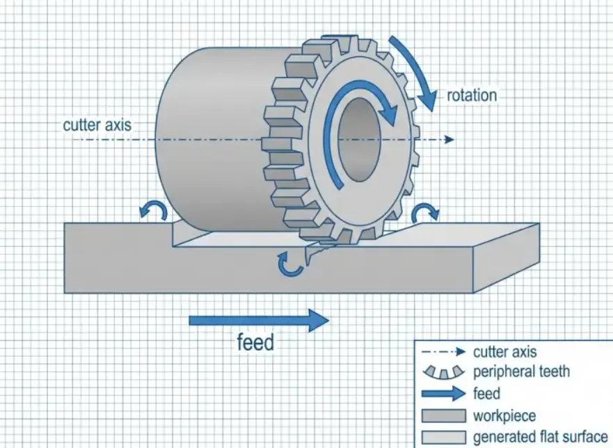
Plain milling
Slot Milling – Slot milling is used to produce slots. The tool has multiple cutting edges that enable it to produce channels and grooves in the workpiece.
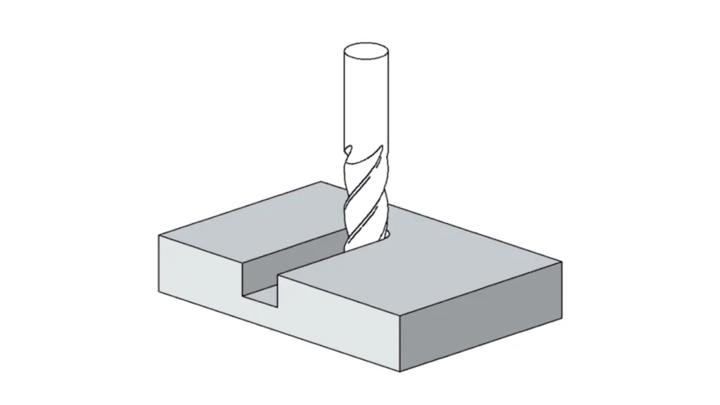
Slot milling
Form Milling – The cutters in form milling are specifically shaped to produce special geometries. The custom-shaped cutters are commonly used to manufacture rounded profiles and recesses.
Gang Milling – Gang milling is done by a set of cutters fixed on the same arbor. The cutters are positioned such that they produce several parallel surfaces simultaneously.
Side Milling – Side milling uses a tool with teeth on its periphery to generate vertical walls. It is a standard peripheral-milling operation.
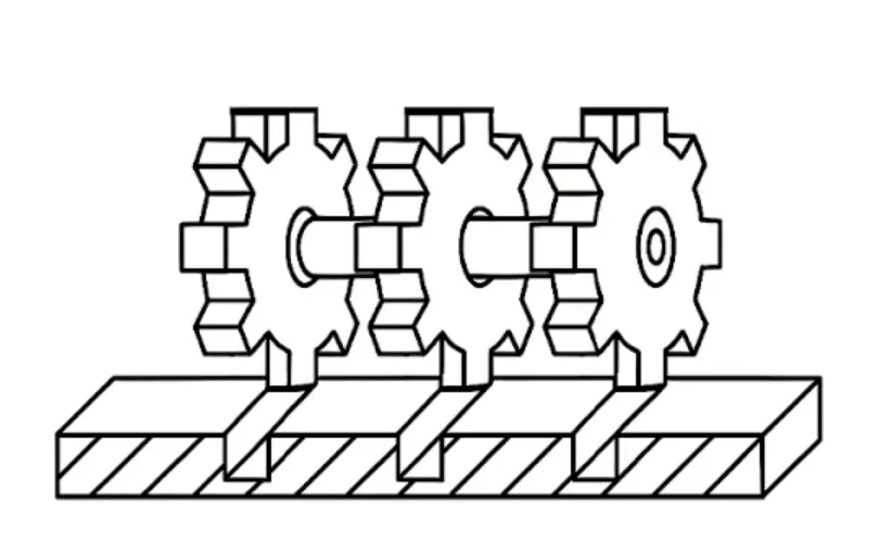
Gang milling
Straddle Milling – Straddle milling is similar to gang milling, only that it is limited to two cutters. As shown in the diagram below, it features a pair of side milling cutters fixed to one arbor.
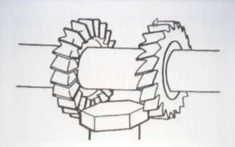
Straddle milling
Important Cutting Parameters in Peripheral Milling
Important peripheral milling parameters include axial depth, radial engagement, cutter diameter, runout, and chip load. The data supplied by the tool supplier should be adjusted for the specific machining circumstances.
Axial Depth – Axial depth is the engagement between the workpiece and cutter, measured along the cutter axis. If it is too much, expect issues such as overheating and tool deflection.
Radial Engagement – This is the width of the cutter engaged with the workpiece. It may also be indicated as a percentage of the cutter diameter.
Cutter Diameter – A cutting tool draws its stiffness from its diameter. Thinner tools are more prone to deflection than thicker ones.
Runout – Runout is a situation when a cutting tool deviates from its desired rotation axis. Some teeth do more cutting than others do. This has a serious effect on accuracy and surface finish.
Chip Load – Chip load usually refers to the feed per tooth. If feed per tooth is too low, the tooth can simply rub against the material. A too-high feed per tooth can cause edge chipping. Milling experts manage these risks by controlling the number of teeth, feed rate, and spindle speed.
Material Considerations in Peripheral Milling
Aluminum, steel, stainless steel, nickel alloys, cast iron, and plastics can be peripheral milled. However, each demands a different machining strategy concerning cutting speed, tool engagement, and coolant management.
Aluminum Peripheral Milling
Aluminum is best machined using positive-rake tooling and high speeds. Lubrication or coolant can help minimize built-up edge and heating.
Steel Peripheral Milling
Peripheral milling of alloy and carbon steel is mostly about balancing heat generation and edge strength. Cut interruptions and weld zones can trigger edge chipping. Using an adequate roughing allowance is an important strategy.
Lower radial tool engagement and the relevant finishing methods may be necessary when milling heat-treated or hardened steel.
Stainless Steel and Nickel Alloy Peripheral Milling
Stainless steel is prone to work hardening if the tool dwells. Therefore, unnecessary dwelling should be avoided. It is also worthwhile to apply the correct chip evacuation method and cutting parameters.
For nickel machining, the high cutting forces and heat generated should be managed by rigid clamping and sufficient cooling.
Cast Iron Peripheral Milling
The short chips and potential abrasive dust from cast iron milling require attention. Dust/fitlration control and the right tooling choice are effective measures.
Plastics Peripheral Milling
Overheating can melt plastics during peripheral milling. The machinist should support the workpiece firmly and use sharp tools.
It is also recommended to allow the machined part to return to a normal, stable temperature before taking the final measurements – some plastics are temperature-sensitive.
When to Use Peripheral Milling
Peripheral milling is a good option when making shoulders, step features, outside contours/profiles, and edge preparation.
Shoulders and Step Features
Shoulder cutting in peripheral milling produces a vertical wall alongside a face. It is important when establishing bearing seats, steps, fixture lands, and mold boundaries.
Outside Contours/Profiles
The milling technique is preferable when creating features such as covers, brackets, structural profiles, and rails.
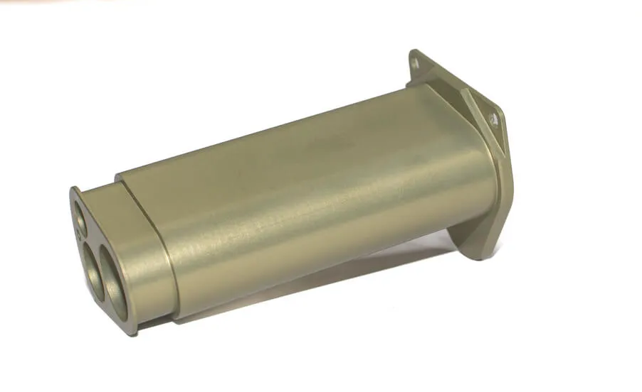
Milled outside contour
Heavy cuts for outside contours can be counterproductive – planning for a smooth finishing pass is recommended.
A 4-axis or 5-axis milling machine may be necessary for additional tool access or consistency in deep walls, tight radii, or hard-to-reach areas.
Edge Preparation
The peripheral milling strategy is worth considering for rails and edges precisely aligned with another datum. Sometimes, surface area covered is secondary to the alignment accuracy required – face milling gives way to peripheral milling.
Design Tips for Quality Peripheral Milling
Support thin walls, realistic internal corner radii, enough room for the tool, well-defined tolerances, and sticking to standard sizes – these are design strategies that can minimize the lead time and cost when your peripheral milling design lands on the shop floor.
Support Thin Walls: A large, narrow vertical wall can deflect under machining forces if unsupported. The right machining strategy and the use of support are recommended countermeasures.
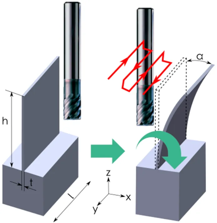
Thin wall deflection
Realistic Internal Corner Radii: As you design your part, remember that rotary cutters are incapable of producing perfectly sharp internal corners.
Enough Room for the Tool: Allowance should not be limited to the cutting edge. Other parts of the tool require space too – body, holder, and chip movement.
Well-Defined Tolerances: Tolerances and datum should be clearly defined for flatness, parallelism, and wall position.
Standard Sizes: Use standard tool sizes, material thickness, and feature sizes where they meet the design requirements to minimize lead time and machining costs.
Tools That Can Be Used in Peripheral Milling Applications
The quality of peripheral milling depends on the type of tool used- side-and-face milling cutters, shell mills, indexable shoulder cutters, solid carbide end mills, High-feed, and modular cutters can be used in the process.
Side-And-Face Milling Cutters
These cutters are used to manufacture grooves, slots, and deep shoulders. Unlike a standard mill, a side-and-face milling cutter has teeth on the side and circumference. Cutting shock is minimized.
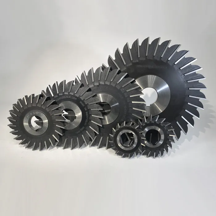
Side and face milling cutters
Shell Mills
Shell mills are specified for repeated large stock removal because they commonly come with replaceable carbide inserts. Tougher grades of these cutters are available for cutting steel and aluminum.
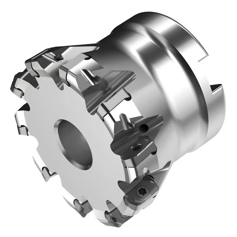
Shell mill
Indexable Shoulder Cutters
These cutters use replaceable inserts to give consistent performance, specifically in repeat shoulder machining.
Solid Carbide End Mills
Solid carbide end mills provide hardness, stiffness, and wear resistance. The cutters feature variable pitch and helix to reduce chatter. These peripheral milling tools are commonly used to produce batches, contours, and slots.
High-Feed Cutters
These cutters use a small entering angle to deliver shallow axial cuts. They are ideal for shallow roughing.
Modular Cutters
These are other versatile peripheral milling tools – a single holder carries several interchangeable extensions that can be carried in a single toolholder setup. This creates the flexibility necessary for different machining applications.
Peripheral Milling vs Face Milling
The main differences between peripheral milling and face milling is the tool orientation and the applications.
As can be seen in the diagrams below, the axis of rotation for the tool in face milling is oriented perpendicular to the workpiece surface.
For peripheral milling, the orientation is parallel.
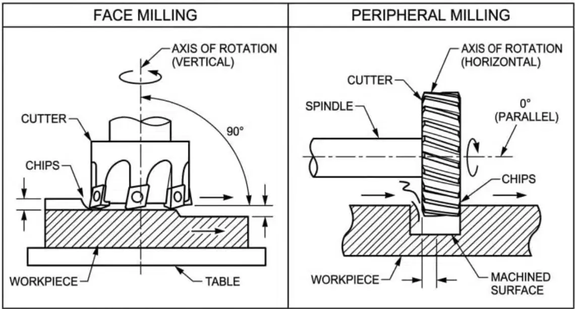
Face milling vs peripheral milling
The table below expounds on the differences that mostly emanate from the tool orientation to the workpiece: main cutting edges, force concerns, surface finish, and common application.
| Feature | Peripheral milling | Face milling |
|---|---|---|
| Tool Axis Orientation | Parallel to the machined surface | Perpendicular to the machined surface |
| Main Cutting Edges | Teeth on the outer circumference of the cutter | Peripheral edges and cutter face |
| Typical force issue | latera/radial deflection | Axial loading |
| Surface Finish | More prone to deflection | More ideal for broad finished surfaces |
| Common Application | Profile contours, side steps, slots | Broad flat surfaces |
Troubleshooting Common Peripheral Milling Problems
Burring, poor flatness, chatter, witness marks, and insert chipping at entry are potential issues in peripheral milling. Since the causes are known, various measures are applied to ensure the surface finish and dimensional accuracy are maintained.
The table below summarizes the problems and suggested fixes.
| Peripheral milling Issue | Possible cause | Suggested fix |
|---|---|---|
| Burring | Unsupported workpiece High edge pressure at the insert exit | Cutter offset adjustment Check workholding Check exit conditions |
| Poor flatness | Inadequate workpiece support Machine alignment error | Workholding verification Spindle-to-table squareness verification |
| Chatter | Weak clamping, excessive tool overhang | Stiff clamping, minimized tool overhang |
| Witness marks | Runout (difference in insert heights) | Insert seating reset |
| Insert chipping at entry | Unsuitable chip thickness Poor cutter positioning Excessive entry shock | Controlled entry conditions and cutter position |
In Conclusion
Peripheral milling is a versatile and widely used machining process. It produces contours, edge features, shoulders, slots, and grooves. The process’s main advantage is its versatility, defined by a range of cutter choices and edge features it can develop.
Manufacturers struggle to find the right cutting parameters, tooling type, material type, and overall machining strategy. An experienced machining service provider takes care of risks such as tool deflection, work hardening, and built-up edge.
In your next part design and processing, the goal should be to achieve the required tolerances and process seamlessness by following the best practices of peripheral milling.
You cannot afford to allow guesswork when producing features such as slots, profiles, and shoulders. Our CNC milling services team is always ready to discuss your design specifications and deliver accurate, durable, and cost-effective parts the first time.
Contact us today for a detailed response within 24 hours.
Resources
[1]https://www.sciencedirect.com/science/article/abs/pii/S0263436815300044
[2]https://www.sciencedirect.com/science/article/abs/pii/S0924013697001271