
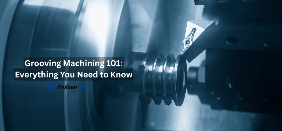

Grooving machining is a cutting technique that uses specialized tools to cut narrow grooves on a workpiece. Although it’s called a grooving tool, you can use it for cutting slots and recesses on a workpiece.
In this guide, you’ll learn about the main grooving techniques, including external grooving and micro grooving with tool selection, material guide, and how to fix common machining challenges.
What is Grooving Machining?
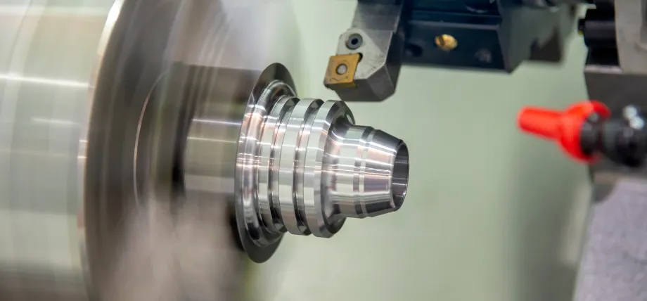
Grooving machining is a technique used to cut narrow grooves or recessed channels into a workpiece as a result of material removal. In mechanical engineering and metal parts, these grooves are important because they serve as
- Housing for O-rings and seals
- Holders for snap rings
- Thread reliefs
- Lubrication passage
- Accurate alignment in assembly parts
It is part of CNC turning and enables the creation of precise channels with controlled widths, depths, and profiles according to your design requirements. You can also create grooves using CNC mills that have indexable grooving inserts.
How Does the Grooving Machining Process Work?
Grooving machining is essentially a material removal process done on a rotating workpiece. All grooving processes have the following common steps:
- Setup: This is the first step and involves securely clamping the machine spindle to ensure stability during machining.
- Tool positioning: involves resting the grooving tool a few mm away from the workpiece at the required diameter and axial location.
- Groove cutting: It is the actual process of feeding the insert radially into the rotating workpiece at a controlled feed rate and cutting depth.
In CNC lathes, this process requires CAM software that converts the groove part design into a machine-readable G-code. The G-code guides the machine to control critical parameters like spindle speed, feed rate, and even the tool path.
The critical part of the process is flushing away chips, and the grooving tool geometry is designed to specifically remove chips easily. Using any other insert, like a typical lathe insert, can cause chip evacuation issues, rough surface finish, and worst cases, damage to the grooved channel.
What Are the Different Types of Grooving Machining Techniques?
The following are the different types of grooving machining methods you can use for manufacturing and production environments, depending on the groove geometry, workpiece orientation, and functional requirements of the final product.
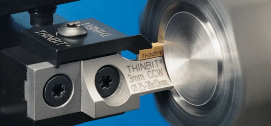
External Grooving
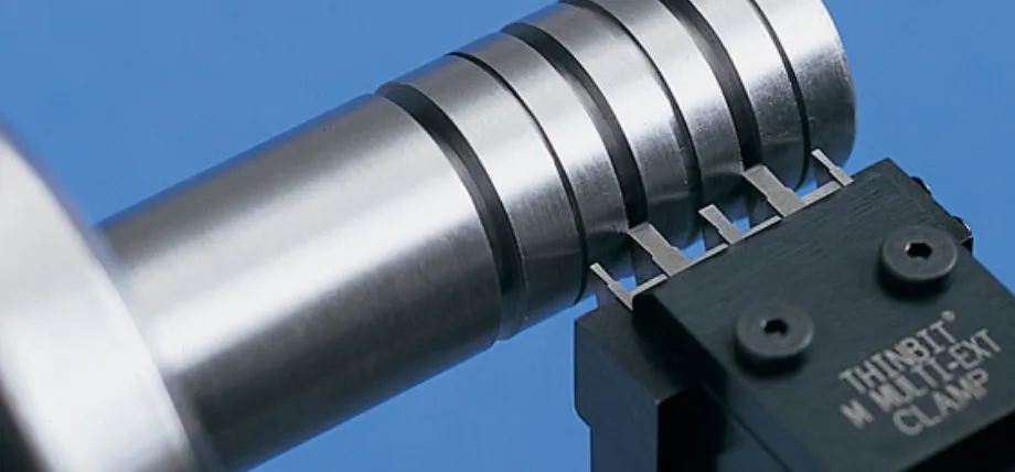
You can apply the external grooving machining process to create recessed features on the outer diameter (OD) of a cylindrical component. This technique is used to manufacture snap-ring grooves, seal grooves, and shaft undercuts.
Internal Grooving
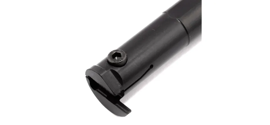
If you need to create grooves inside a bore or hollow cylindrical workpiece, such as an O-ring in hydraulic cylinders, snap-ring grooves in housings, and circlip grooves inside bearing bores, internal grooving is the most suitable machining method. You should use an internal grooving tool, which is designed as a boring bar with a slim cutting head that extends into the bore and feeds radially outward.
Radial Grooving
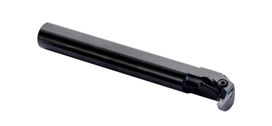
If the grooving tool feeds perpendicular to the axis of the workpiece while moving directly into the material’s radius, it is referred to as the radial grooving machining technique. You can use this feed direction in
- External grooving on outer diameter surfaces
- Internal grooving inside bores
Face Grooving
Face grooving is a specialized technique part of grooving operations that specifically creates concentric circular grooves on the flat end face of a rotating workpiece. The grooving tool is inserted axially into the face of the part.
If your grooves are deep (more than 30 mm), multiple roughing passes are performed before the final finishing cut.
Common Applications:
- Flanges
- Pump faces
- End plates for O-ring or gasket seating
Axial Grooving
Axial grooving has a slightly technical difference; it involves cutting grooves along the length of a rotating workpiece. Axial grooving is used to create long, straight grooves on shafts or cylindrical parts.
Axial grooving is useful for applications requiring thread relief and lubrication channels.
Micro Grooving
Micro grooving is a high-precision technique specifically with sub-millimeter-sized cutting tools to produce extremely fine grooves in the micrometer range. It requires specialized micro-tools with sharp cutting edges and minimal runout to maintain accuracy.
Micro grooving is not a common machining process and is reserved for industries like electronics, medical devices, and aerospace, where miniature components demand tight tolerances and intricate surface features.
Plunge Grooving
Plunge grooving is the most common grooving method. Here, the grooving tool is fed radially (perpendicular to the axis). Plunge grooving is more efficient in creating external or internal grooves of specific widths and depths in a single pass or multi-pass operation.
Plunge grooving is widely used for O-ring grooves, snap ring seats, and sealing features.
Multi-Step Grooving
If the cutting width or depth of a single insert is less than the desired groove width or depth, multi-step grooving is used. Unlike plunging, the grooving tool performs multiple overlapping passes (radial or axial) to achieve the desired groove geometry.
Contour Grooving
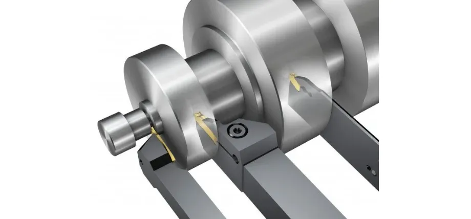
Contour grooving is an ideal grooving operation for curved profiles, producing non-linear grooves. The tool path is programmed to match the contour shape you provide, and this allows the creation of a recess that is curved recess. Contour grooving is better than standard grooving for curves because plunge methods for grooving cannot achieve the same level of functionality and aesthetics.
Ramping
Ramping has a slow entry where the tool enters the material at an angled path instead of a plunge. This reduces initial cutting forces, tool stress, and the risk of chipping, making it useful for harder materials and when high feed rates are needed.
Peck Grooving
Peck grooving involves feeding the tool in short, intermittent increments. This is done to remove chips at regular intervals and clear debris. This method is useful when your design has deep grooves, where continuous cutting could cause poor chip evacuation, resulting in poor surface finish and overheating.
Circular Interpolation Grooving
Circular interpolation grooving uses CNC circular movement commands and is specifically used for arc-shaped grooves. It is useful when you need to create features that are difficult to achieve with the standard linear movement of the grooving tool.
It is commonly used for creating rounded grooves, cam profiles, and sealing surfaces.
Parting
You can use the parting technique if you need to cut the workpiece entirely through to separate the finished product from the remaining bar stock. The narrow grooving tool continues the cutting process until the diameter reaches zero.
Undercutting
This technique is applied to machines behind a shoulder or at the end of a threaded section to provide clearance for mating components. The dimensions of an undercut design are engineered with specifications for width, depth, and corner radius to ensure proper fit and assembly.
Thread Grooving
This is also known as a thread undercut. It is a relief groove that is machined at the end of a threaded section to provide a runout area for the threading tool. A narrow plunge-style grooving insert is used to produce relief grooves that match the dimensions specified in the engineering drawing.
O-Ring Grooving
Cryogenic Grooving
You can use cryogenic grooving machining method for grooving materials such as titanium, Inconel, and stainless steel by delivering liquid nitrogen or CO2 directly to the cutting zone. This is an ultra-low temperature cooling method that extends tool life two to four times compared to other machining techniques for some titanium and nickel alloy applications.
Multi-Axis Grooving
This method can be used for the production of aerospace, turbine components, advanced hydraulic manifolds, and other highly complex precision parts, as 4-axis and 5-axis grooving machining centers allow grooving tools to access the workpiece from multiple angles.
What Machines and Tools Are Required for Grooving Machining?
You can select machining equipment depending on the groove design, workpiece geometry, and production requirements. CNC lathes are applicable for external grooving, internal grooving, face grooving, and parting operations on cylindrical or rotational components.
What Are the Main Types of Grooving Tools?
| Tool Type | Application | OD/ID/Face | Compatible Machine |
| External grooving tool | Snap ring grooves, seal grooves, and undercuts | OD | CNC lathe, turning center |
| Internal grooving tool | O-ring seats and circlip grooves in housings | ID | CNC lathe, boring machine |
| Face grooving tool | Flange sealing areas and pump faces | Face | CNC lathe, turning center |
| Lathe grooving tool | General-purpose grooving and parting operations on rotating components | OD/ID/Face | Manual lathe, CNC lathe |
| Parting tool | Separating finished parts from bar stock | OD | CNC lathe, turning center |
External Grooving Tools
A blade-style holder of the external grooving tool is fixed securely to the machine turret, positioning the grooving insert on the outer diameter of the workpiece precisely. The groove width is directly defined by the insert width for single-plunge operations. Wider grooves can be machined through multiple overlapping passes.
Internal Grooving Tools
Internal grooving tools are available with a boring bar-style body and a compact insert head angled outward for cutting inside bores. The boring bar style is available in either round or square shank configurations. The coolant channels in the shank deliver coolant directly to the cutting area, removing chips efficiently in blind-bore applications.
Face Grooving Tools
Face grooving tools allow the groove insert to feed axially into the workpiece face at a specific radius, as it is designed with a curved or offset cutting head.
Lathe Grooving Tools
There is a wide range of lathe grooving tools designed for grooving and parting operations on both manual and CNC lathes. When selecting a lathe grooving tool, the choice should be based on specific application requirements.
- Insert width: The grooving insert width should closely match the desired groove width for accurate cutting.
- Groove depth: This is important when you need deep external grooves; blade-style or parting style tool holders are preferred due to their extended reach and stability.
- Internal Grooving: CNC machinists prefer boring bars with minimal overhang to maintain stability and prevent tool deflection.
- MGEHR and MGIVR style holders fitted with MGMN grooving inserts for general-purpose grooving
- Blade-style lathe grooving tools are used for deep groove applications
- Quick-change lathe tools are applied in high-production environments
Parting Tools
These are designed with the narrowest practical blade width, ranging from 2 mm to 4 mm, to reduce material waste or kerf during separation of the finished product from the bar stock.
What Are Grooving Inserts and How Do You Select Them?
The quality of the surface finish, tool life, and the accuracy of dimensions are determined by the grooving inserts. They are replaceable cutting components mounted in the tool holder during grooving machining. Furthermore, you should consider the chipbreaker design for efficient chip control.
For example,
- PVD-coated grooving inserts provide strong adhesion resistance and good flank wear performance at medium to high cutting speeds.
- Wear resistance of CVD-coated inserts is higher for stable and high-speed machining of steel and cast iron.
- Sub-micrograin carbide inserts with PVD TiAIN coatings reduce build-up edge formation when machining stainless steel or nickel-based alloys.
| Insert Type | Profile | Best Material | Application |
|---|---|---|---|
| Full-radius insert | Rounded or semicircular groove floor | Steel, stainless steel | O-ring grooves, stress relief grooves |
| Flat-bottom insert | Flat groove floor with sharp corners | Aluminum, mild steel | Snap-ring grooves, thread reliefs, standard grooving operations |
| V-profile insert | Grooves with angled sidewalls | Steel and cast iron | Thread grooving, chamfered groove entries |
| PVD-coated carbide insert | Multiple profile options | Stainless steel and exotic alloys | High-speed grooving and medium to high-speed cutting operations |
| CVD-coated carbide insert | Multiple profile options | Steel and cast iron | High wear applications under stable cutting conditions |
| Uncoated carbide insert | Multiple profile options | Aluminum and non-ferrous metals | Low-speed grooving and machining of softer materials |
How Do You Choose the Right Grooving Machine for Your Operations?
| Criteria | Considerations |
|---|---|
| Groove orientation | CNC lathes are used for outer diameter (OD) grooves,Face grooves on turning centers with live tooling,Axial grooves applied on milling machines or broaching equipment |
| Part diameter and length | The swing capacity of the machine and distance between centers must be sufficient to accommodate the workpiece dimensions |
| Groove depth | Machines with adequate Z-axis travel and highly rigid tool-holding systems are required for deep grooves to maintain stability during cutting |
| Production volume | For high volume production: CNC turning centers with automated bar feedersFor low volume production: Manual lathes or standard CNC lathes |
| Material hardness | Machines with improved spindle rigidity are required for materials harder than 45HRC, including stable workholding and CBN inserts with optimized cutting parameters. For high-pressure or cryogenic cooling applications, through-spindle coolant systems are required |
| Tolerance requirements | CNC machines with thermal compensation capabilities and spindle bearing systems with high accuracy are required for precision tolerances such as ±0.01 mm. |
What Materials Can Be Groove Machined?
You can use any machinable material depending on your purpose, considering the difficulty and tooling requirements of that material.
| Material | Machinability | Recommended Insert | Key considerations |
| Mild steel | Good | PVD-coated carbideFlat bottom insert | Should apply standard cutting conditions for reliable chip control and stable machining performance |
| Stainless steel (304/316) | Moderate | Sub-micrograin carbide with PVD TiAIN coating | Need sharp cutting edges and a consistent feed rate |
| Aluminum (6061,7075) | Excellent | Uncoated carbide with high rake geometry | Efficient coolant flow and proper chip evacuation are required for soft and adhesive chips |
| Titanium (Ti-6AI-4V) | Difficult | Fine-grain PVD-coated carbide | Cryogenic cooling is beneficial as low thermal conductivity concentrates heat at the insert edge |
| Inconel and superalloys | Very difficult | Ceramic or CBN inserts | Cryogenic or laser-assisted grooving techniques are useful due to high cutting force and severe work hardening |
| Cast iron | Good | CVD-coated carbide | Highly wear-resistant grooving inserts are required due to abrasive material characteristics |
| Hardened steel (>45 HRC) | Difficult | CBN inserts | A highly rigid machining setup is required with lower feed rates and effective through-coolant delivery |
| Engineering plastics | Good | Sharp-edge uncoated carbide | Prevent thermal distortion by lower cutting speeds. |
What Are the Applications of Grooving Machining?
| Industry | Groove type | Example Part | Function |
| Hydraulics and Pneumatics | O-ring grooving and internal grooving | Hydraulic cylinder bore Valve body | Sealing pressure Fluide containment |
| Automotive | External grooving and thread grooving | Engine shaftTransmission component | Snap-ring retention and thread relief |
| Aerospace | Face grooving, micro grooving, and multi-axis grooving | Turbine diskFuel manifold | Sealing seating, cooling passages, and reducing the weight |
| Oil and Gas | External grooving and internal grooving | Pipe coupling Valve stem | Groove-lock pipe connections and sealing |
| Medical devices | Micro grooving | Surgical implantsCatheter components | Surface texturing for tissue integrationPrecision fitting |
| General manufacturing | Axial grooving and parting | Shaft keyway Bar-fed machined parts | Transmission of torquePart separation |
Common Challenges in Grooving Machining and How to Overcome Them
The challenges of grooving machining include tool wear, maintaining dimensional accuracy, and surface finish.
Tool Wear and Breakage: Grooving inserts are narrower than standard turning inserts. Therefore, the entire radial cutting force is concentrated on a small cutting edge, causing insert failure during the CNC machining process of hard materials. You can avoid this issue by
- Properly matching the insert grade to the workpiece material.
- Remaining feed rates within the manufacturer’s recommended range
- Replacing grooving inserts before flank wear exceeds 0.3 mm, or earlier, depending on the material grade, workpiece material, and required tolerance.
Dimensional Accuracy Problems: Tool deflection during the internal grooving machining process causes variations in groove dimensions. You can correct deflection-related defects and improve dimensional accuracy of the groove by performing a finishing pass at a lower feed rate after the rough machining process.
Bad Surface Finish: When resonance develops between the grooving tool and the workpiece, chatter produces repetitive vibration marks on the groove surface. You can enhance the surface finish by,
- Reducing tool overhang
- Adjusting spindle speed
- Incorporating a short dwell cycle at the bottom of the groove
Chip Control Problems: Chips of ductile material, such as aluminum and austenitic stainless steel, can be accumulated inside the groove, leading to damage and breakage of grooving insert. This issue can be resolved by using aggressive chipbreaker designs combined with high-pressure coolant directed into the groove base.
Tool Vibration
In internal grooving, tool vibration is one of the most common challenges you have to face, as the boring bar must extend deep into the bore with minimal support. You can minimize this issue by using an anti-vibration boring bar equipped with an internal damping system.
Material Deformation
Micro grooving methods and workpieces with thin walls are highly sensitive to elastic springback and thermal distortion. You can maintain dimensional accuracy of thin sections by supporting them with mandrels or steady rests. Furthermore, sharp positive-rake grooving inserts and reduced feed rates are used to minimize cutting forces while limiting material deformation within acceptable tolerances.
How Much Does Grooving Machining Cost?
| Cost Factor | Lower-cost Scenario | Higher-cost Scenario |
| Material | Aluminum and mild steel- Machine easily and produce lower insert wear | Titanium and Inconel – Require slower cutting speeds, additional passes, and cause rapid insert wear |
| Groove complexity | Snap ring groove with a single plunge cut | Internal groove with tight tolerances – requires multiple passes and peck grooving cycles |
| Tooling | MGMN carbide grooving inserts with general-purpose toolholders | Customized inserts, anti-vibration boring bars, and through-coolant tooling systems |
| Machine time | Production of a high-volume CNC lathe with bar feeders and short cycle times | Low-volume manual machining or multi-axis (5-axis) grooving method |
| Insert consumption | A single grooving insert edge can typically machine hundreds of parts under normal conditions. | Tool life is significantly lower; one insert edge may only machine a few parts |
| Tolerance requirement | Standard grooves with tolerance around 土 0.1 mm | O-ring or micro grooving methods require tolerances around 土 0.01 mm |
CNC Machining Services
Proleanmfg provides high-quality custom machining for all aluminum alloys, aluminum castings, and brass machining services. We also provide post-machining services like improving surface finishes through mechanical treatments on the grooving parts.
Standard CNC machining tolerances for aluminum parts are around 0.025 mm, but it depends on part geometry and machining process. Precision grooving can achieve even lower tolerances.
Request a free quote today!
Conclusion
You can apply a range of grooving methods from CNC lathe to micro grooving, depending on the material. The results of the grooving machining process depend on selecting the correct grooving tool, grooving insert, and groove geometry, along with the most suitable machining method. This precise selection directly influences the dimensional accuracy, component durability, and the ability to maintain consistent production cost.
Frequently Asked Questions
External grooving tools, internal grooving tools, face grooving tools, lathe grooving tools, and parting tools are used on CNC lathes, turning centers, or milling machines. These tools are fitted with replaceable grooving inserts.
Grooving tools are widely used on both manual and CNC lathes for operations such as external grooving, internal grooving, face grooving, and parting.
Grooving is a specialized cutting process used to create narrow channels, recesses, or slots with specific widths and depths. Turning is a general machining process that removes material continuously from the outer surface of a rotating workpiece to reduce the diameter.
The cutting tool feeds perpendicular to the workpiece axis and moves directly into the radius of the component during radial grooving. But grooves are created parallel to the rotational axis of the workpiece by axial grooving.
The grooves are created on the outer diameter (OD) surface of a cylindrical workpiece by the external grooving, while grooves are machined inside bores or hollow workpieces by internal grooving.
What Are Grooving Inserts and How Are They Different from Turning Inserts?
Replaceable cutting inserts are grooving inserts that are specifically designed for groove machining by concentrating the cutting force on a smaller cutting edge to produce groove dimensions precisely. These are available in multiple profiles, including full-radius, flat-bottom, and V-profile designs. But these are narrower than turning inserts, which are intended for broader material removal and contour turning operations.