
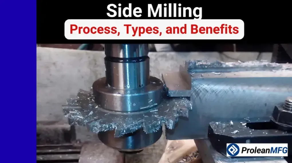

Side milling is a popular CNC milling operation, which is defined by the use of the milling cutter’s side cutting edge. The radial engagement of side milling cutters with the workpiece produces precise features such as grooves and bevels.
As a type of peripheral milling, side milling is effective when some machining parameters are identified and handled properly. The most important ones are feed rate, depth of cut, spindle speed, and chip load.
A good machining partner ensures the correct application of this machining strategy. Alongside the machining parameters, important measures or considerations are chatter, heat buildup, chip evacuation, and material type.
All these and other details about this type of milling are covered in this article. Continue reading for more details.
What is Side Milling?
Side milling is a popular milling operation characterized by material removal from the side of the workpiece. This milling approach produces vertical surfaces. The side milling cutter meets the workpiece radially.
The side milling cutter is designed to produce vertical walls and precise edge geometry. So, this is a preferable operation when parts require wall accuracy. For instance, it is ideal for transmission parts, machine brackets, and frames.
What Are the Three Types of Milling?
The three types of milling are peripheral milling, end milling, and face milling.
Peripheral milling has cutting teeth or edges on the cutting tool’s outer diameter. The workpiece surface and the axis of the cutter are parallel to each other.
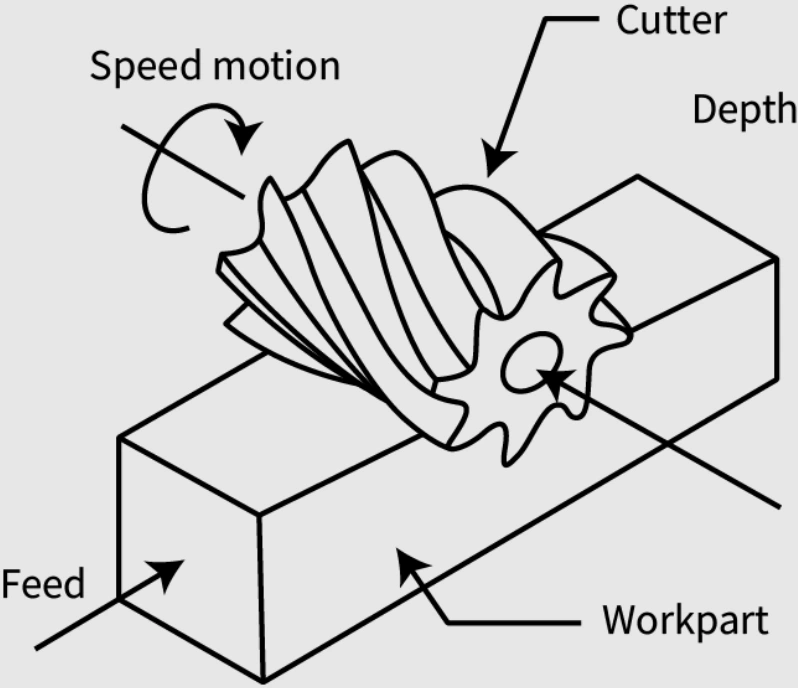
In end milling, the cutting edges are on the sides and the tip. Therefore, cutting is done in multiple directions.
For face milling, the cutting edges are on the face and periphery. However, most of the cutting is done by the face cutting edges. The workpiece surface is perpendicular to the tool’s axis.
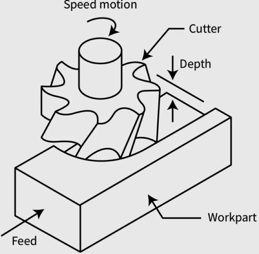
Side milling falls under the peripheral milling category.
How Side Milling Works
The workpiece and side milling cutter are placed in such a way that material can be moved along a vertical plane. With a predetermined path and spindle speed, the cutter is ready to cut the workpiece and produce the desired geometry.
The specific side milling steps include equipment positioning, radial cutting, axial cutting, and finishing.
Equipment Positioning – The first step is to secure the workpiece. The side milling cutter is then positioned such that its cutting edge and the side of the workpiece are in contact. Fixturing is also professionally done to prevent tool chatter.
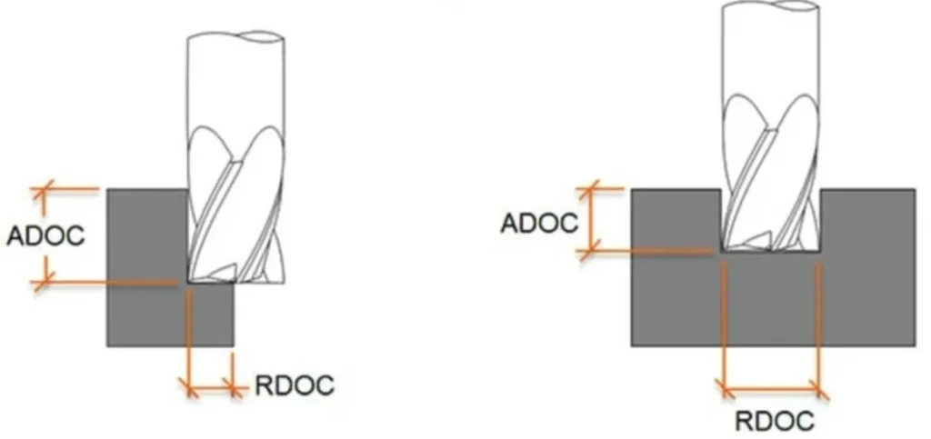
Radial Cutting – This is for the cutting width. The side milling cutter moves radially into the workpiece to a specified width. This width, also called the radial depth of cut (RDOC), influences the cutting force and chip thickness.
Axial Cutting – For the axial depth of cut (ADOC), the cutter moves in an upward or downward direction. This type of cutting is associated with tool wear and heat generation.
Finishing – The cutting process is complete when the surface finish and geometric accuracy are according to the design. One of the precision machining tactics for this is high-speed finishing.
The key to the entire process is to ensure proper perpendicularity control. That means the base surface and vertical walls are square to each other.
Types of Equipment Required in Side Milling
Several machine capabilities, tools, fixturing solutions, and toolholders are necessary for successful side milling. Here are more details about these requirements.
CNC Milling Machine
Vertical machining centers (VMCs) and horizontal machining centers (HMCs) are on top of the list. Multi-axis machining centers can also be used in the process.
Cutting Tools
End mills are widely used in side milling. The different types of side milling cutters are covered in more detail in the section below.
Fixturing
Robust fixturing and workholding are required to manage the significant radial forces generated. Common fixtures for the side milling process include;
- Magnetic/vacuum fixtures for flat workpieces
- Custom-designed fixtures for non-standard shapes
- Soft jaws
Toolholders
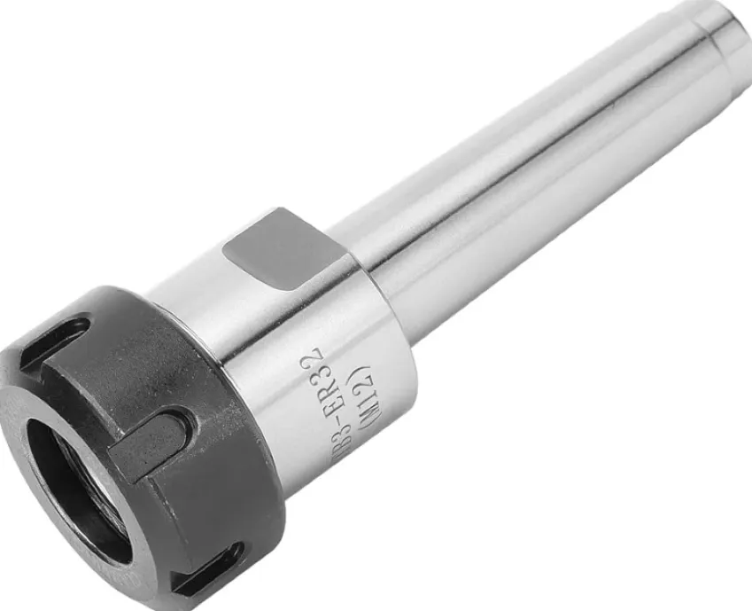
The most common toolholders in side milling processes include hydraulic chucks, end mill holders, ER collet chucks, and shrink-fit holders.
Types of Side Milling Cutters
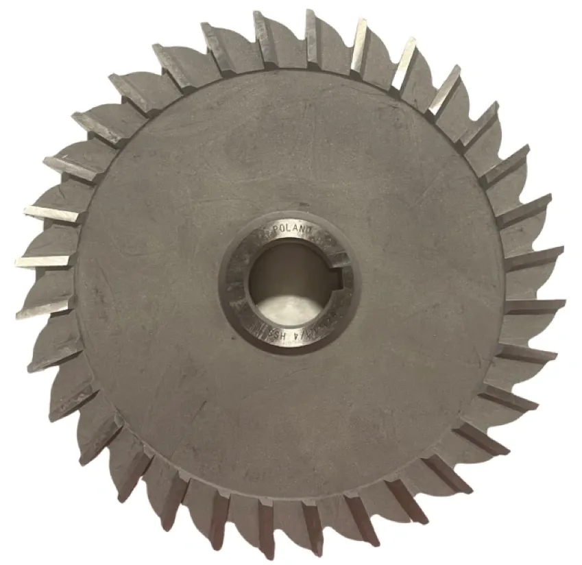
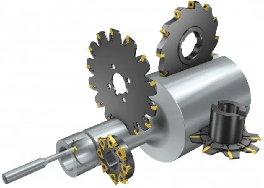
Side milling cutters come in different designs, the most common being plain side milling cutters, staggered-tooth cutters, and side-and-face cutters. Others are concave cutters, convex cutters, half-side cutters, interlocking cutters, and inserted-tooth cutters.
Plain Side Milling Cutters
Plain side milling cutters are designed for straight vertical surface machining. They are commonly used for simple cutting operations, especially where precision and a smooth finish are priorities.
Staggered-Tooth Cutters
These cutters are built for removing substantial material and handling larger chips. Their alternating left- and right-hand teeth minimize cutting resistance and enhance chip evacuation.
Side-and-Face Cutters
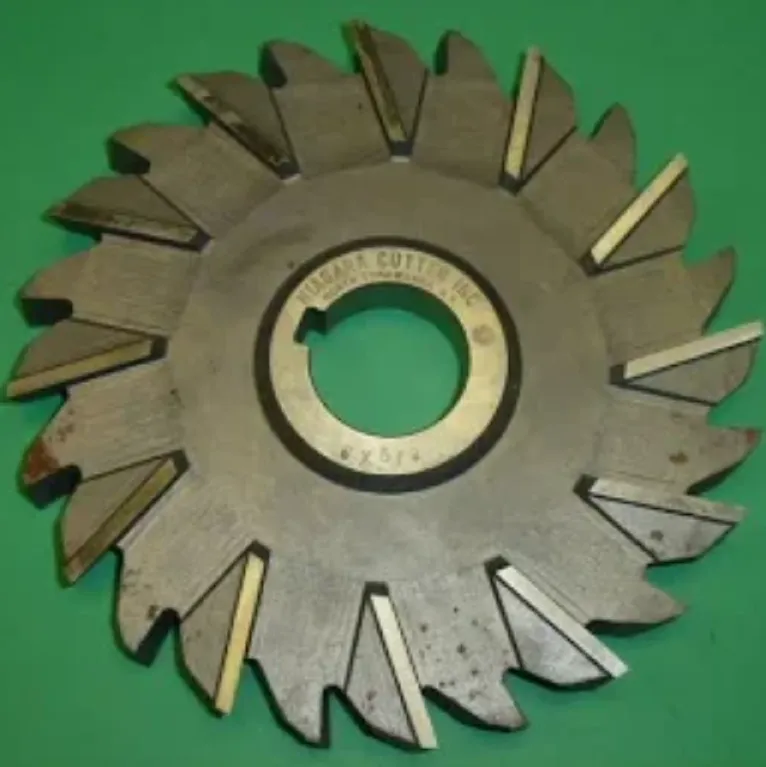
As the name suggests, the cutters can effectively cut adjacent surfaces. The cutter teeth are on the sides and the face. Due to this design, these cutters can produce grooves and slots in a single pass.
Concave Side Milling Cutters
These cutters are used to generate concave profiles. We can use such types of cutters to machine curved internal surfaces, especially those with consistent radii. They are also effective in producing gear blanks.
Convex Side Milling Cutters
Convex cutters are the opposite of concave cutters. Machinists use them to produce rounded external or convex profiles. A popular application of the cutters is form milling, which can also be performed by form cutters.
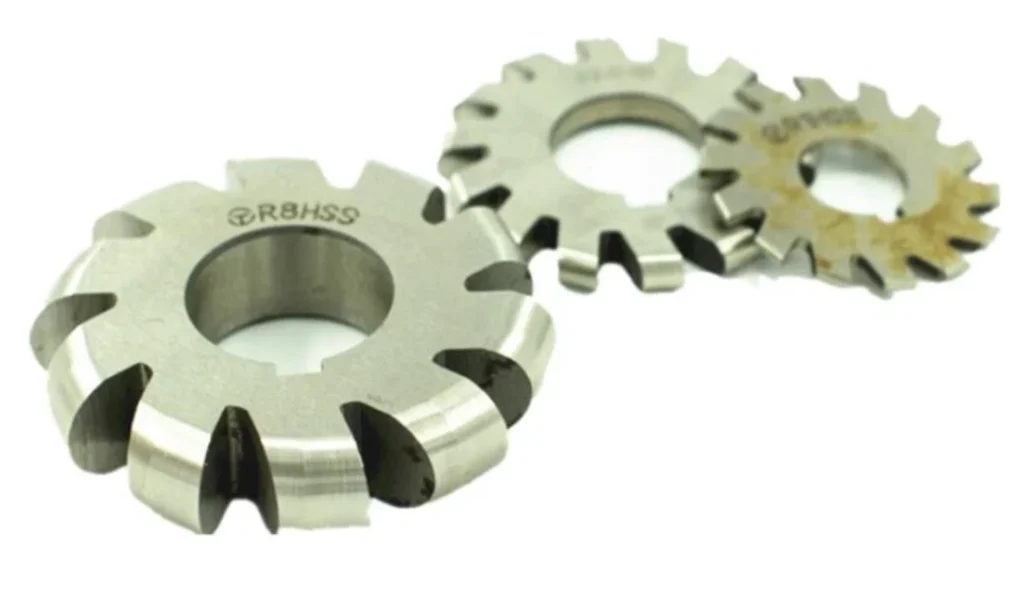
Half-Side Milling Cutters
These cutters are one-sided, meaning they are designed to cut only one side of a workpiece. Their teeth are limited to one face and the periphery.
Interlocking Side Milling Cutters
Interlocking side milling cutters are built for making slots with an accurate width apart. They are ideal for precision spacing. Machinists only have to adjust the spacers in the cutter to achieve precise cutting, for instance, in gang milling operations.
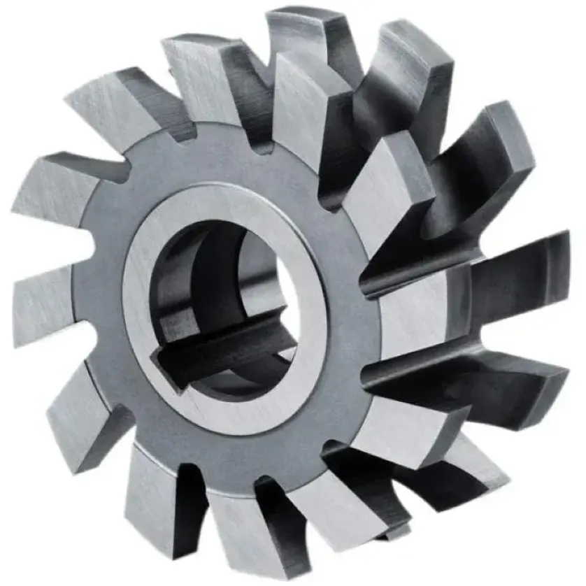
Inserted-tooth Side Milling Cutters
Fitted with replaceable cutting inserts, these types of cutters are suited for heavy-duty or high-volume machining. They are also relatively economical to run.
Note that carbide cutters outdo other types in this market. Their thermal stability and wear resistance are unmatched. Manufacturers particularly opt for these cutters for high-batch production.
Different Side Milling Operations
The main side milling types are bevel side milling, cross milling, contour side milling, and flat side milling. Others are half‑side milling, plain side milling, and straddle milling.
Bevel Side Milling – This operation uses angled or beveled tool spindles. The cut walls are also angled or beveled. Machinists use this operation to produce angled edges, chamfers, and V-grooves.
Cross Milling – For this milling type, a pair of side mills is used to machine two parallel surfaces simultaneously. It is an accurate and consistent method for machining vertical surfaces.
Flat Side Milling – This is more common or standard than the others. It produces vertical shoulders or surfaces.
Contour Side Milling – This version produces complex or curved surfaces. It is common in the production of irregular geometries, particularly in form milling.
Half‑Side Milling: This operation uses a half-side milling cutter to machine one side of the workpiece. The strategy can also be used when the cutting space is limited.
Plain Side Milling: A plain side milling cutter is used for this operation. The periphery teeth are effective in producing simple vertical surfaces.
Straddle Milling: The milling type comprises an arbor carrying a pair of side milling cutters. Spacers are placed between the milling cutters so the machining operation produces two parallel surfaces.
The choice of a side milling operation depends on the machining objective, which we have shared alongside the methods.
The Common Types of Materials Used in Side Milling
Like other milling types, this method is widely used on common machining materials such as aluminum, stainless steel, carbon steel, copper, brass, and even engineered plastics.
You will mostly come across side-milled 5xxx and 6xxx series aluminum due to good machinability and favorable chip formation. With the expert machining control from our team, built-up edge formation should not be a source of concern.
Many projects will also require the strength of steels and stainless steels. For such, we use sturdier tools and slower cutting speeds.
Here’s a table of a summary of the materials.
| Material | Properties and Considerations for Side Milling |
| Aluminum (6061, 7075, 5083) | Clean chips, very machinable |
| Stainless Steel (304, 316) | Heat build-up. Prone to work hardening. Moderate cutting speeds and sharp tools. |
| Carbon/Alloy Steel (1018, 4140) | 1018 is easy to machine, but coated carbide tools are required for 4140 |
| Copper/brass | Soft, superior surface finish. Use sharp tools. |
| Engineered plastic | Avoid heat buildup. Use sharp tools. |
| Composites (CFRP, GFRP) | Highly abrasive. Specialized tooling and dust extraction methods required. |
| Inconel/titanium | Poor thermal conductivity. Tough to machine. Slower machining speeds. Rigid setup. |
| Tool steel (D2, O1) | Abrasive and hard. Slower machining speeds. Carbide-coated cutting tools. |
Important Side Milling Parameters
The most important parameters for this process are;
- Feed Rate: Measured in mm/min, this parameter indicates the tool speed along the contour. The feed rate should be neither too fast nor too slow.
- Spindle Speed: It is the rotational speed of the side milling cutter. It is given in revolutions per minute (RPM). The manufacturer’s recommendations and the type of machining material are key determinants of spindle speed.
- Axial Depth of Cut (ADOC): This is the cutter’s depth of engagement along the flute length. While higher ADOC translates to a higher material removal rate, it can enhance tool deflection and damage.
- Radial Depth of Cut: This parameter measures the proportion of the tool’s diameter that engages with the workpiece. Since RDOC impacts heat generation and cutting forces, it should be optimized.
- Coolant Quality: Coolant concentration should be correct to enhance thermal management and chip evacuation.
- Tool Size: The cutter’s size, mostly the diameter, determines the ideal tolerances, ADOC, and RDOC.
- Cutting Speed: The cutting speed refers to the surface speed at which the workpiece and side milling cutter engage. Since it is a major contributor to tool wear, the recommended values should be adhered to.
As explained, these parameters greatly affect the machining process performance and results, so the machinist should optimize them.
For instance, while cycle times are shorter with higher feed rates, the tool load is higher. Also, increasing the depth of cut, as it enhances productivity, compromises the surface finish.
Advantages and Limitations of CNC Side Milling
Side milling is renowned for producing versatile features on a wide variety of materials; among other advantages, it has several limitations worthwhile to consider.
Advantages of side milling
- Material and feature versatility
- Suits roughing and finishing operations
- Excellent dimensional accuracy
Limitations of side milling
- Prone to tool deflection
- Heat buildup in hard materials
- Difficult to evacuate chips
Where To Use Side Milling?
Here are instances when using side milling makes the most sense:
- Step milling or offsetting on a component
- Making keyways or slots on a part
- Finishing edges on structural components
- Machining shoulders and vertical faces
Common Side Milling Challenges
Using the side milling cutter comes with challenges such as tool wear, dimensional errors, burr formation, and chip recutting.
- Fast Tool Wear
Like in other machining operations, tool wear is a common challenge in side milling. Mitigation measures include a thorough inspection approach comprising dimensional checks and visual inspection.
For enhanced tool durability, harder tools such as high-speed steel (HSS) and titanium nitride (TiN) are used.
- Dimensional Errors
Tool vibration in side milling operations can promote dimensional errors. It could be due to poor clamping, worn tooling, or high RDOC. Rigid workholding and optimized cutting parameters usually solve this problem.
- Burr Formation
Burr formation is common on aluminum, mild steel, and other ductile materials. Using sharp tooling and optimizing toolpath exit angles are popular mitigation strategies. Secondary deburring operations can be performed for critical parts.
- Chip Recutting
Chip recutting degrades surface finish and the tool’s cutting edge. It can be a serious issue when machining slots and deep pockets. Remedies include using the correct chip load settings and coolant flow.
Factors Affecting Side Milling Quality & Precision
The main factors affecting the quality and precision of side milling are the cutting tool condition, machine condition, cutting parameters, and workholding rigidity.
| Factor | Explanation |
| Cutting Tool Condition/Geometry | A worn tool is one of the most common causes of poor dimensional accuracy and surface finish. An incorrect helix angle affects the tool’s capability to cleanly cut the workpiece. |
| Machine Condition | Positional errors can emanate from backlash and spindle runout. |
| Cutting Parameters | The balance of ADOC, RDOC, feed rate, and spindle speed determines the amount of load subjected to the cutting tool |
| Workholding Rigidity | Poor clamping and locating strategies can introduce vibrations and shifts in the workpiece, affecting tolerances. |
How to Ensure Optimal Side Milling
There are several ways to ensure optimal side milling, but the machinist should ideally start with rigid workholding and good tool selection. Nothing can compensate for that. Not even the best milling cutters.
Other than that, the following five best practices ensure quality side-milled parts;
- Minimizing cutting tool overhang
- Proactive management of tool wear
- Machining simulation before full manufacturing
- Appropriate use of climb milling
- Using coolant effectively
Side Milling Compared to Other Machining Operations
We can compare side milling type with often-confused-with alternatives, namely face milling, end milling, slot milling, and straddle milling.
Side Milling vs Face Milling
Side milling uses the periphery of the cutter to produce vertical faces and shoulders. It forms an axial engagement with the workpiece surface.
Face milling is different because it uses cutting edges on the tool’s face. The engagement with the horizontal surface is axial.
Side Milling vs End Milling
While side milling uses the peripheral cutting edges, end milling relies on the tip and side edges. The machining results are mostly vertical walls and complex contours for side milling and end milling, respectively.
Side Milling vs Slot Milling
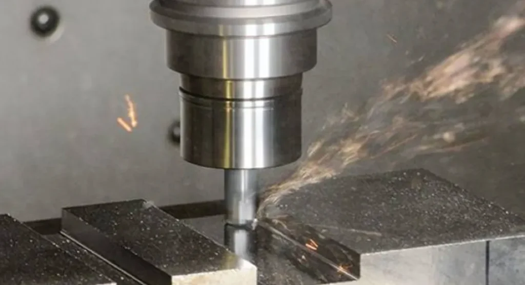
The major difference between the two milling methods is that while side milling is about how the cutter is oriented relative to the workpiece surface, slot milling is defined by the type of feature produced.
Side Milling vs Straddle Milling
Side milling uses one cutter, while straddle milling uses two side cutters. You could consider straddle milling more efficient in producing symmetrical, parallel surfaces.
Conclusion
The versatility and reliability of side milling make the process suitable for producing profiles, walls, and slots in various applications. Standard milling may not deliver the precision and steadiness of this milling type in difficult cuts.
You may need side milling operations for different features required in parts for aerospace, automotive, electronics, heavy machinery, and other areas. You will get quality parts with excellent surface finish and tight tolerances.
For efficient and precise side milling, contact our technical team. You will get all your questions about CNC milling services answered and a free quote provided.
FAQs
Yes, side milling is a common manufacturing process for making vertical steps, shoulders, and grooves in industries such as aerospace, tooling, automotive, and machinery.
Side milling is not necessarily expensive. The cost can be manageable since the process uses common milling cutters, and machining strategies can be optimized.