
Bevel machining, or beveling, is a machining process that involves cutting and shaping the corner of a workpiece where two faces meet by creating a sloping or angled surface. Beveling comes in many forms, depending on material and application. It serves many purposes, such as functional benefits and removing the sharp corners for safety. Therefore, any wrong tool, angle, or incomplete drawing can cause rework and material waste.
This simple guide covers what beveling is, its types, standard bevel angles, beveling tools, and how it differs from chamfering.
Bevel machining, or beveling, is a machining process that helps to cut and shape the corners of a workpiece’s two faces by creating a sloping or angled surface.
This simple guide helps you to understand what beveling is, its types, standard bevel angles, beveling tools, and the differences between beveling and chamfering.
What Is Bevel?
A bevel is an angled or sloped surface created along the edge of a workpiece. It is created by cutting the edge at an angle other than 90.°This process removes the material from the edge by forming a gradual slope and softens the intersection between the surfaces.
A bevel serves three main purposes: weld preparation, assembly fit-up, and edge safety. The most critical role is weld preparation. It organizes the setup, which joins the two pieces of metal.
This angled edge is prepared on the metal before welding. It controls three main factors, such as filler volume, joint geometry, and weld penetration depth.
This process removes the material from the edge by forming a gradual slope or chamfer and softens the intersection between the surfaces.
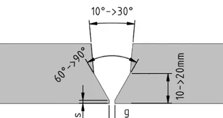
V-Groove Angle and Dimension Diagram
A small mistake of 2°in angle can result in the changed behavior of the weld pool. The two main issues are that the metal is not fully joined at the bottom, and there is an extra weld. It involves complete removal and rewelding.
Bevels are used to configure the material by achieving specific functions in engineering. Removing sharp edges can make the product look better, and obviously, it has safety benefits too.
However, precision is always significant here. That sounds simple! Therefore, the edge finishing ultimately enhances the safety of the part and its durability.
However, precision is always significant here. Therefore, the edge finishing ultimately enhances the safety of the part and its durability.
If the beveled angle is just 3° off the required spec, it causes an issue named as interference. Moreover, a 90°sharp edge can hurt workers. The beveled edges can reduce the stress on sharp corners in machine components like shafts and fasteners. This helps to improve fatigue resistance, making the parts more long-lasting and durable.
What Are the Types of Bevel (Beveling)?
Bevel types are based on material type and joint strength requirements. Below are the commonly used types of bevel:
Single Bevel
A single beveled edge has an angle on one side of the workpiece, while the other side remains flat. It is a simple and cost-effective machining method. A single bevel helps penetrate deeper and creates a strong joint, especially in thick materials. However, issues such as excess stress concentration, misalignment, and poor weld penetration can happen if not performed correctly.
The single bevel is helpful to penetrate deeper and create a strong joint, especially in thicker materials.
Double Bevel
A double bevel is an angled cut on both edges of a workpiece, forming an X-shaped profile. Welding is applied to both sides of the joint. It allows deeper weld penetration and is ideal for thick metal sections. A double bevel requires less weld material than a single bevel. However, it can lead to cracks, poor fusion, and weak weld strength if performed incorrectly.
However, if it is wrongly done, then it can create cracks, poor infusion, weak infusion, and weak weld strength.
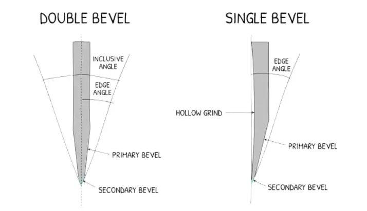
Double Bevel vs Single Bevel Knife Edge Diagram
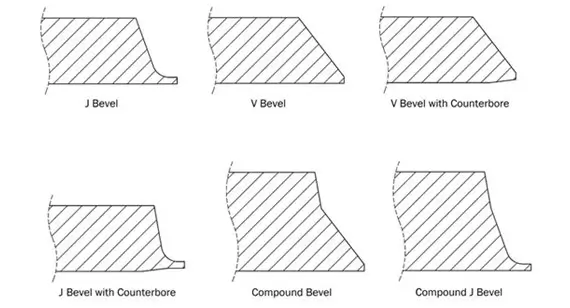
J-Bevel
A J-bevel is a concave and curved bevel profile. It forms a material like the letter “J” shape with a curved groove. J-bevels help reduce weld volume and heat input, which in turn minimizes distortion in thick materials.
J-bevel requires minimum heat during welding. It also helps to reduce distortion in thick materials. It is commonly used in pressure vessels and nuclear components. If it is replaced by a V-bevel, it can change the structure of the metal in the heat-affected zone.
Compound Bevel
A compound bevel uses two angles, named the primary bevel angle and the secondary skew angle, along the same edge. The cut is made in two angular directions at once.
The manual beveling tools have completely failed here in achieving precision. So, an angular grinder cannot accurately produce the same compound bevel every time. For this, a 5-axis CNC machine in G-code is ideal to produce the same cut on every part.
The manual compound bevel can create an angle variation of ±5° or more. This creates gaps in pipe joints, angled connections, and mitered frames. It requires extra filler welding to fit up during welding.
Relief Bevel
A relief bevel is added to cutting tool edges in order to reduce friction and heat buildup during machining. This is often overlooked in tool design. This can lead to tool wear and higher machining costs per part.
| Bevel Type | Profile | Best Application | Weld Volume | CNC Required |
| Single Bevel | Half-V | T-joints, one-sided access | High | No |
| Double Bevel | X-profile | Thick plate butt welds | 50% less than single | No |
| J-Bevel | Curved concave | Pressure vessels, nuclear | Lowest | Yes |
| Compound Bevel | Two-angle simultaneous | Pipe saddles, mitered frames | Variable | Yes 5-axis only |
| Relief Bevel | Back-side slope | Cutting tool edges | N/A | No |
Bevel vs Chamfer: A Confusion That Causes Real Production Problems
Bevels, chamfers, and fillets are different edge treatments. These are still getting confused in technical drawing every week. This confusion leads to expensive manufacturing mistakes, such as part assembly, strength, safety, and overall cost.
If a drawing involves a bevel, but the machinist creates a chamfer instead due to similar chamfer specifications. The part may appear visually correct. But it can fail functional inspection due to poor assembly and improper weld prep.
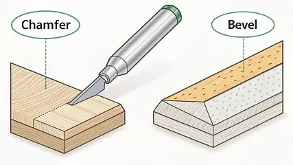
Chamfer vs Bevel Edge Difference
The incorrect selection can increase the cost significantly. This impact multiplies across the entire production run.
The selection of the correct edge treatment is crucial to ensure parts fit properly, perform reliably, and remain cost-effective to produce.
| Feature | Bevel | Chamfer |
| Length | Full edge length | Short corner break only |
| Angle reference | From the original face | Assembly lead-in, edge deburring |
| Drawing callout | Angle + depth or angle + length | Usually 45° × dimension |
| CNC tool | Bevel milling cutter, angle cutter | Chamfer mill or countersink |
| Cost of confusion | Wrong weld prep → failed inspection | Wrong lead-in → assembly interference |
A bevel is an angled edge used for welding or structural strength, with the full angle specified in technical drawings. In contrast, a chamfer is usually used to remove sharp edges or corners for safer handling or easier assembly, and is typically defined using a standard 45° × size format.
Beveling and chamfering can both be performed in the same CNC program on the same part. However, they serve different engineering purposes.
Standard Bevel Angles
The actual standard bevel angles are set up with proper welding codes. But they are not usually 45° per side. If you ask about the bevel angle in any fabrication shop, the answer is often 45° due to simplicity. It does not mean 45° is the best angle; rather, it is commonly used because it is easier to set up manually.
| Bevel Angle | Joint Configuration | Governing Standard | Why This Angle |
| 30° per side (60° included) | V-groove butt weld | AWS D1.1 | Optimal fusion with minimum filler |
| 37.5° per side (75° included) | V-groove, higher penetration | AWS D1.1 | Better root access on thicker material |
| 45° per side (90° included) | Heavy plate double V | General fabrication | Maximum access, highest filler volume |
| 22.5° per side | Narrow gap welding | Pressure vessel codes | Minimum filler, minimum heat input |
| 10–15° | J-bevel root face | ASME Section IX | Pipe welding, controlled heat input |
Bevel Specification Completeness Checklist
| Specification Element | Weld Prep | Assembly Fit-up | Edge Finishing | If Missing |
| Bevel angle | Must specify | Must specify | Must specify | Wrong geometry, failed inspection |
| Angle reference face | Must specify | Must specify | Optional | Three different cuts from the same number |
| Root face dimension | Must specify | Not needed | Not needed | Blow-through or incomplete fusion |
| Root gap | Must specify | Not needed | Not needed | Wrong penetration depth |
| Surface finish (Ra) | Must specify | Optional | Not needed | Weld porosity from oxide trapping |
| Bevel depth or length | Must specify | Must specify | Must specify | Wrong material removal |
The default cost of using 45° is often hidden. In structural steel work, such as AWS D1.1, a 37.5° per side bevel is common for some V-groove welds. The correct bevel is usually around 37.5°, not 45°, in structural steel work like AWS D1.1. The use of 45° makes the groove wider, increases welding time, and causes heat distortion. However, a small increase in weld volume and labor time can add up costs on large-scale projects.
However, this adds thousands of dollars in extra welding costs on a large project.
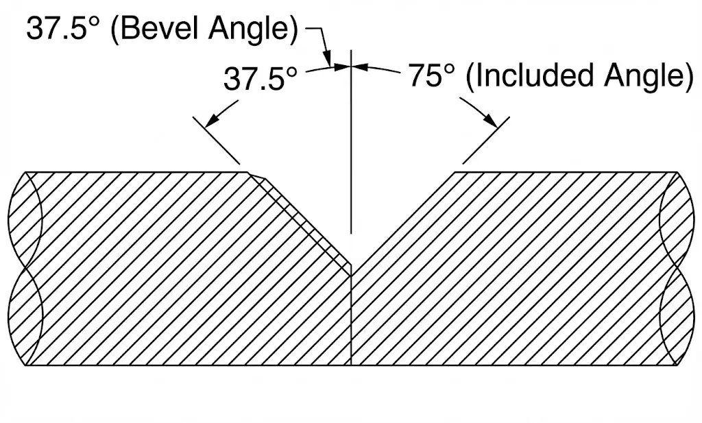
Bevel Angle and Included Angle Diagram
Beveling Tools: Why the Right Tool Prevents a Rework Cycle
The selection of the wrong beveling tools is a cost issue rather than a quality issue. And this increases with every part in the production run.
Bevel Milling Cutter
The bevel milling cutter is the main CNC machining tool for bevel machining. This bevel machining tool is available in fixed angles such as 30°, 45°, 60°, and 90°. Therefore, Carbide-tipped versions keep their shape better, especially on tough beveled metal edges during cutting. TiAlN-coated carbide tools further extend tool life for stainless steel or hard materials.
An uncoated HSS bevel milling cutter used on stainless steel can harden the surface during the first cut. This can damage both the tool and the surface finish.
Angle End Mill
An angle end mill is more versatile than a bevel cutter. This tool can create a bevel within a multi-operation CNC program without needing a tool change. However, it is not as effective as a dedicated bevel cutter for making deep cuts.
Portable Beveling Machine
A portable beveling machine is necessary for pipe ends and structural plates. It is used when the CNC setup is impractical. This machining process produces beveled cuts within ±1–2° under ideal conditions. Accuracy depends on factors such as material type, tool condition, and machine setup rigidity. However, the accuracy reduces around ±3–5° due to tool wear and operator fatigue. It is also influenced by operator skill and overall process stability.
This machining process involves beveled cuts within ±1–2° under ideal conditions. But the accuracy reduces to ±3–5° with the tool wear and operator fatigue.
However, the ±3° angle variation can cause inconsistent weld groove shapes on a large production run of 500 parts. This leads to variable weld penetration, and some components can fail during the weld inspection.
Angle Grinder
An angle grinder is the last resort for bevel machining. It is quick to set up but very difficult to control accurately. It produces a rough surface that can trap oxides and lead to weld porosity. Therefore, it is not recommended for welding prep in structural or pressure-critical applications.
This can lead to a porous weld due to the ground bevel surface. This requires the full removal of the joint and re-welding. Ultimately, it can cost up to 10× more than machining the bevel correctly in the first place.
Beveled Metal: What Changes Across Different Materials
The most expensive mistake in bevel machining is the selection of bevel metals. Because the same bevel angle behaves differently when cut into different materials.
| Material | Biggest Bevel Risk | Root Cause | Prevention |
| Mild Steel 1008–1018 | Burr on the exit edge | Interrupted cut exit | Climb milling, sharp tool |
| Stainless Steel 304/316 | Work hardening at the cut zone | Tool dwell during cutting | Maintain feed rate, never stop mid-cut |
| Aluminum 6061/7075 | Built-up edge on the cutter | Aluminum adhesion to the tool | Sharp, polished carbide, climb milling |
| Titanium Ti-6Al-4V | Heat buildup destroys the tool and the surface | Low thermal conductivity | Reduce speed 40–50%, flood cool |
| Hardened Steel >40HRC | Rapid carbide degradation | Material hardness | CBN inserts or EDM only |
| Inconel 625/718 | Extreme tool wear | Work hardening + heat | TiAlN carbide, low speed, high feed |
Common Mistakes in Bevel Machining
Specifying Angle Without Reference Face
The common mistake comes from how the angle is measured, as different conventions are used in practice. In machining and welding, angles can be defined from the face, from the edge, or as the included joint angle between both sides.
The common mistake is how the angle value is measured. There are three different cuts measured from the face, from the edge, or from the included joint angle. This causes wrong geometry, failed fit-up, and re-machining of the entire batch.
Missing Root Face and Root Gap
The bevel angle of the missing root face and root gap is an incomplete weld prep callout. The result of this can be incomplete fusion and weld blow-through.
Using Manual Tools for Compound Bevels
The two continuous angular cuts are required for a compound bevel. The result can be fit-up gaps at every joint.
Wrong Material-Specific Approach
The use of steel bevel parameters on stainless steel can harden the surface. This makes it harder to machine. Moreover, the use of carbide tools on titanium can burn the edge. This results in wasted parts and damaged tools in the same process.
Over-Beveling Thin Material
The material thinner than 6mm with a 45° bevel removes so much material.
The material thinner than 6mm with a 45° bevel removes excessive material. This reduces edge strength in thin-sheet designs before welding. This makes the joint weaker even before welding begins. The parts fail structural testing as a result.
Key Takeaways:
A bevel mistake causes a rework cost that is more than the first time. Manual bevel tools vary between ±3–5°. Define an angle with the root face and root gap together. Weld quality is directly impacted by the way the material behaves.
ProLean MFG: Bevel Machining Where the Cost of Getting It Wrong Is Unacceptable
ProLean MFG treats every bevel as a true engineering requirement that affects the final performance of the part. If it is done wrong, it can cause problems later in fitness, strength, and function.
Our CNC machining services deliver single bevels, double bevels, J-bevels, and compound bevel geometry held to ±0.5° angular tolerance, across prototype quantities and full production runs alike.
Send us your drawing, and we will review it by identifying the bevel risks. Our expert engineers recommend 5-axis strategies to eliminate potential issues after assessing.
Send us your drawing. We will tell you exactly where the bevel risk is. And how we will eliminate it.
Frequently Asked Questions
A bevel is an angled or inclined surface on the edge of a workpiece. It is created by cutting the material at an angle other than 90° with a precise slope.
Basic single-angle beveling is not hard to learn, particularly with simple tools. However, beveling is difficult and risky when achieving precise, consistent bevels in CNC machining.
A bevel is an angled surface following an angle that requires welding or structural strength. A chamfer, on the other hand, is a sharp edge or corner that is removed using the standard 45° × size format for assembly and safer handling.
The common mistakes of bevelling are:
– Unclear angle reference
– Using manual tools
– Missing weld prep details
– Ignoring material behavior, such as heat and work hardening issues