
The two main reasons why people choose CNC machining over other simple and cheap manufacturing methods are its precision and repeatability. And, at this level, the range of CNC machining tolerances is minimal, which means almost exact parts. That’s why CNC machining is popular for producing parts that can be assembled perfectly and perform as expected.
Due to not following tolerance standards properly, many industries waste a lot of money and time for reworking and fixations. By understanding and following machining tolerances and related standard charts clearly, you can avoid many of those possible mistakes during the early stages of design.
What are CNC Machining Tolerances?
It’s obvious that you’ll always get a deviation between the actual dimensions and the nominal dimensions of a part. When working with real projects, you can never bring those two values to a single point. But you can minimize them and maintain them within accepted ranges by following proper tolerance guidelines.
The definition of CNC machining tolerances is how much an actual dimension of a CNC-machined component is allowed to deviate from its nominal (expected) dimension.
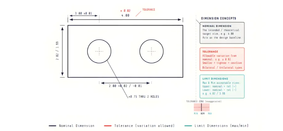
Representation of the Actual Value and Tolerances of a Part
You cannot completely prevent the deviations, but you can minimize them by using industry best practices and referring to standard CNC machining tolerances to maintain these deviations within acceptable limits.
Difference Between Nominal Dimension and Tolerance
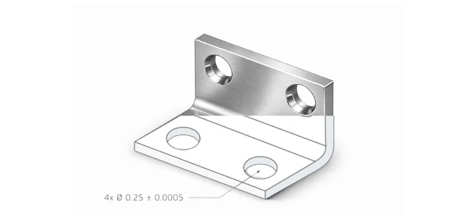
Precision Bracket with Tight Tolerances
An example of the standard notation for indicating dimensions is given below.
Ø10.00 mm ±0.05 mm
Your theoretically expected value of the diameter of the finished hole is 10 mm, which is also known as the nominal dimension. But the actual value can vary between 9.95 mm and 10.05 mm, also known as the tolerance.
Importance of CNC Machining Tolerances in Manufacturing
Impact on Part Fit and Function
In manufacturing, you mostly create individual parts separately and then do the assembly. If you need to assemble them smoothly and with proper functioning, you must maintain the tolerances of your parts within allowable ranges.
If the tolerances of your parts are too loose, you’ll get issues like vibration and leakage. Also, if you have unnecessarily tight tolerances, the parts will become difficult or impossible to assemble. To obtain a predictable fit, correct CNC machining tolerances must be used.
Influence on Performance and Reliability
Sometimes, even small dimensional errors can cause unexpectedly large issues with performance and reliability. In many cases, this will result in long-term performance failures and unexpected costs in handling consequences. Examples for such situations include:
- If the shaft is slightly oversized, it can increase friction and heat significantly
- If a bore is misaligned, it can reduce the service life of bearings
- Uneven wall thickness can damage and weaken a pressure component
With precision CNC machining, you can control these risks to a good extent by giving appropriate tolerances. It might increase the initial investment slightly, but it will bring you many long-term benefits and protect you from unexpected failures and risks.
Cost Implications of Tighter Tolerances
Maintaining tolerances within allowable ranges is important. But if you try to go for tighter tolerances that you actually don’t need, it’ll raise machining costs and the overall cost of CNC production unnecessarily. This will increase:
- Machining time
- Tool wear
- Efforts for inspection
- Scrap rate
Therefore, maintaining your dimensions within specified ranges is acceptable and sufficient. You need to balance CNC machining tolerance vs cost, as paying unnecessarily for overengineering is not needed and is also a waste of resources.
Relationship Between Tolerance and Manufacturability
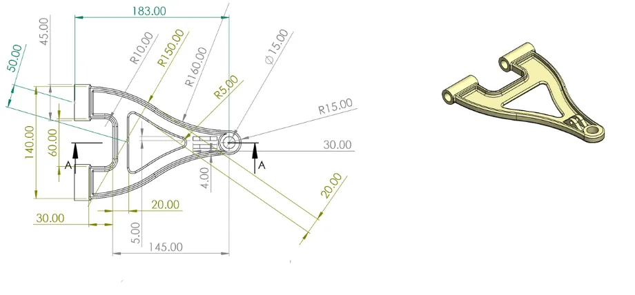
Suspension Component Drawing
Manufacturability is the ease of producing a part repeatedly with consistent properties without excessive effort or risk. If your tolerances are too tight, you’ll face manufacturing challenges such as:
- The range of acceptable machining conditions becomes smaller
- Machines take longer to set up and the process become complex
- Extra cutting or finishing steps may be needed
These factors increase machining time and make the process complex (it can also introduce issues like variation, scrap, or rework). Trying to obtain unrealistic tolerances will also create a sensitive and high-risk process.
If you choose the correct CNC machining tolerances, you’ll obtain a practical balance of both the function and manufacturability. Therefore, your target is not achieving maximum precision; it is to obtain sufficient precision with proper functioning.
Standard CNC Tolerance Ranges and Charts
In the industry, you can find globally accepted limits of tolerances defined for specific applications. These are called standard machining tolerances. Most CNC machining services follow these as the default tolerance ranges when you do not specify your custom values.
Standard Tolerance System (ISO 286)
In general, the typical machine shop capabilities for machining tolerances are:
- ±0.125 mm (±0.005 in) for most linear dimensions
- ±0.25 mm (±0.010 in) for larger or non-critical features
Most of the modern CNC machines can achieve above levels by default. In many cases, they offer a good balance between dimensional accuracy and production cost.
Precision CNC Machining Tolerances
However, some applications need tighter control over dimensions due to safety or performance requirements. In these cases, you can go for precision CNC machining tolerances. Common precision machining tolerance ranges include:
- ±0.025 mm (±0.001 in)
- ±0.012 mm (±0.0005 in)
If you want to achieve these tight tolerances, you need stable machines and high-quality cutting tools. You also have to operate them under controlled environments and inspected under specialized methods. Because of these added complexities, precision parts have higher machining costs compared to parts made with standard tolerances.
CNC Milling Tolerances vs CNC Turning Tolerances
As you might know, CNC milling and CNC turning use different motion systems. Therefore, the level of accuracy that each process can achieve is different.
| Feature | CNC Milling | CNC Turning |
| Typical Part Geometry | Prismatic parts, blocks, plates, and complex 3D surfaces. | Round, cylindrical, or conical components (shafts, pins, etc.). |
| Best-Controlled Features | Slots, pockets, flat surfaces, and hole patterns. | Diameters, threads, and axial symmetry. |
| Typical Tolerance Capability | ±0.025 mm (Standard); up to ±0.01 mm (High-precision). | ±0.02 mm or better (Standard). |
| Surface Finish Capability | Excellent for flat faces; may show “scallop” marks on 3D contours. | Superior for cylindrical surfaces; excellent concentricity and roundness. |
CNC milling is mostly suited for producing prismatic parts and complex 3D surfaces (e.g., blocks, plates, slots, pockets). With milling, you can get:
- Excellent control over flat surfaces and complex geometries
- Typical tolerance range is around ±0.025 mm
- High-precision milling operations can reach up to ±0.01 mm under controlled conditions
CNC turning is ideal for round or cylindrical components. Parts like shafts, pins, and threaded parts are mainly formed using CNC turning. Turning will give you:
- Excellent dimensional control on diameters
- Better concentricity and roundness compared to many milling operations
- Typical tolerance capability of ±0.02 mm or better
Turning can hold cylindrical features more consistently because the workpiece rotates around a fixed central axis, while the cutting tool moves along the length, gradually removing material.
International CNC Tolerance Standards
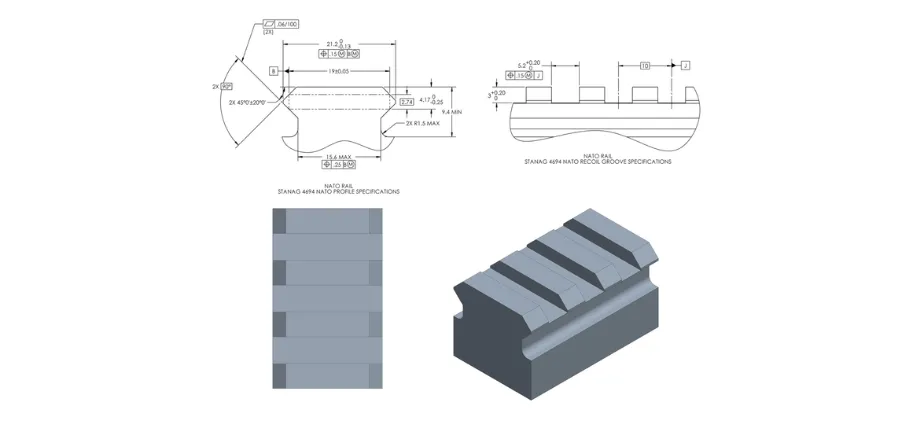
Rail Profile
Since you need to maintain the consistency of tolerances across manufacturers and countries, the best practice is to reference the international tolerance systems. The most widely used standard is based on ISO 286. It defines IT (International Tolerance) grades and standardized fits for holes and shafts.
IT grades specify the allowable dimensional variation for a given nominal size. Common IT grades used in CNC machining span from IT6 to IT10. Lower IT numbers represent tighter tolerances (e.g., IT6 allows variations depending on the feature, ranging from tens of microns to a few microns, IT10 allows wider limits suitable for general machining).
ISO standards also define fit systems using combinations of hole and shaft tolerances.
- Clearance fits allow free movement between parts
- Transition fits may result in either slight clearance or slight interference
- Interference fits create a press-fit between components
By using these standardized systems, CNC machining services can interpret tolerance requirements accurately and achieve predictable functional performance.
CNC Machining Tolerance Charts
There exist industrially used sets of ranges specified for commonly used applications. They are known as CNC machining tolerance charts and you can use them as quick references for commonly machined features.
You must know that these charts are used generally and sometimes you’ll also have to define custom tolerances based on your needs.
Linear Dimension Tolerances
Table 1: CNC Machining Tolerance Chart for Linear Dimensions
| Feature Size Range | Tolerance |
| Up to 25 mm | ±0.025 mm |
| 25 – 100 mm | ±0.05 mm |
| 100 – 300 mm | ±0.1 mm |
Hole Diameter Tolerances
Table 2: CNC Machining Tolerance Chart for Hole Diameters
| Hole Size | Tolerance |
| <10 mm | ±0.01 mm |
| 10–50 mm | ±0.02 mm |
| >50 mm | ±0.05 mm |
Shaft Diameter Tolerances
Table 3: CNC Machining Tolerance Chart for Shaft Diameters
| Shaft Size | Typical Tolerance |
| <10 mm | ±0.01 mm |
| 10 – 50 mm | ±0.02 mm |
| >50 mm | ±0.05 mm |
Angular Tolerances
The generally used angular dimensional tolerances for CNC machining are:
- ±0.5° for general machining
- ±0.25° for precision work
Factors Affecting CNC Machining Precision
Machine capability
Capability of the machine tool – High-quality CNC machines use rigid frames, precision ball screws, and thermal compensation systems. Simpler and cheaper machines can give components with broad tolerance ranges.
Tooling and process parameters
Condition and type of the cutting tool – Worn tools can result in deflection and dimensional drift. Tool geometry also affects the surface finish and size.
Thermal Effects – Both machines and parts can expand when the temperature rises. Those dimensional changes can also add microns of deviation to the component.
Workholding and Fixturing – Poor fixturing causes vibration and movement. Providing stable fixturing improves repeatability of the process.
Environmental and material factors
Material Properties – The cutting behavior of soft plastics is totally different from hardened steel. Some materials spring back after machining, and some expand with heat.
Geometric Dimensioning and Tolerancing (GD&T) in CNC Machining
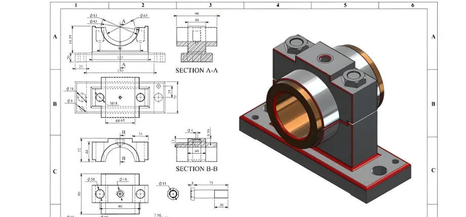
Bearing Housing Assembly Drawing
GD&T (Geometric Dimensioning and Tolerancing) is a system used to control a part’s shape and position (not just its size).
Here, instead of only giving a dimension like Ø10 ±0.01 mm, you can define other dimensional properties like true position, circularity, and flatness.
GD&T focuses on how the part actually functions in an assembly. It allows tight control on critical features and looser control on non-critical ones, so you can reduce machining costs without sacrificing performance.
How to Specify Tolerances on Engineering Drawings
Using clear and consistent tolerances in drawings prevents confusion, rework, and incorrect assumptions during manufacturing. When you give clear requirements, machinists can interpret requirements quickly and produce parts correctly in the first attempt. Some of the best practices you can follow in drawings are:
- Using block tolerances – You can define default limits for all dimensions. They stay constant unless otherwise specified (e.g., X.X ±0.1 mm, X.XX ±0.05 mm, X.XXX ±0.02 mm). This is like providing a consistent baseline across the entire drawing.
- Applying tolerances specific to certain features – When you have critical features that affect fit, alignment, or performance, you can mention their own explicit tolerances directly next to the dimension.
- Avoid overcrowding – Avoiding tight tolerance machining for every feature by default and highlighting only important ones for function.
Good drawings are simple and easy to understand. They also simplify CNC machining cost calculation, reduce quoting time, and lead to more predictable results.
Design Tips to Optimize Tolerances and Reduce Cost
- Using standard CNC machining tolerances whenever possible
- Using tight tolerance machining only for critical features (avoid overengineering)
- Matching tolerances to actual and practical functional needs
- Avoiding extremely thin walls with tight tolerances
- Early communication with your supplier about their tolerance capabilities (this will avoid confusions and unrealistic expectations)
CNC Machining Services
If you’re looking to complete projects that require precise machining of copper or brass, consider partnering with ProleanMFG.
Our services come with consideration for quality and include precision tolerance handling, advanced CNC milling with 5-axis capabilities, exact alloy selection with rapid turnaround for low to medium volume runs.
Reach out today for a free quote and cost-effective solutions to your CNC projects.
FAQs
When do you usually need tight tolerances?
You’ll need tight tolerances when you have sensitive and precise functional requirements like fluid flow control, precise alignment, and assembling motion parts. You usually do not need it for cosmetic surfaces or non-functional features.
How do tolerances affect CNC machining cost calculation?
Tight tolerances increase setup time and require specialized inspection techniques. This directly raises the cost of CNC parts. Tolerance class is considered as one of the largest cost drivers. Two identical (visibly) parts can differ greatly in price due to tolerance requirements.
Do Tighter Tolerances Mean Better Quality?
Not always. Your target should be meeting functional requirements, not chasing the smallest possible tolerance value.