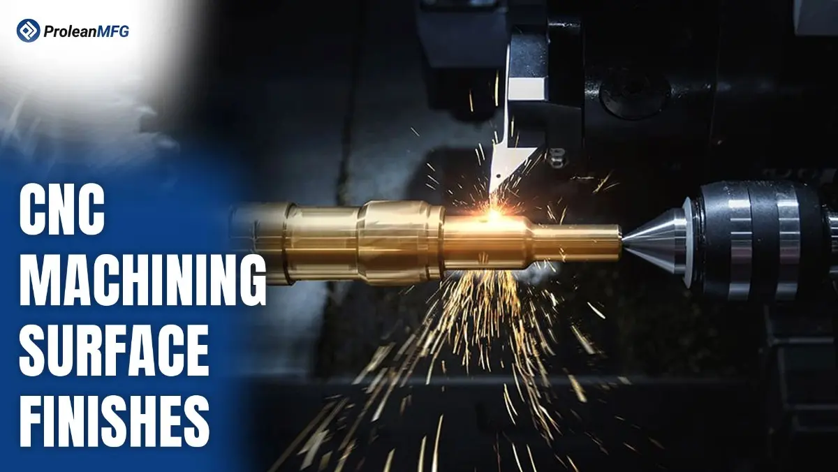

Why does the surface of a machined part matter?
Machining surface finishes show how smooth or rough a part feels and looks after being made. This is the final quality and feel of a surface when the work is done.
A rough cut gear differs from a shiny medical tool. The surface finish changes how a part works, fits with other parts, wears with time, and how it looks.
In CNC and exact making, surface finish is not just an extra detail. It is a must-have thing. For fields where being exact matters, like air travel or medical, the surface quality can make or break a part’s work, life, or meeting safety rules.
You might work in medical, electronics, cars, or air travel. Knowing about standard machining and finishing ways is key. This is not just about the shine. It changes how parts slide, connect, and handle pressure or rubbing.
ProleanMFG engineers care about more than just tight limits. They give solid finishes that meet both technical needs and look standards.
This guide will cover about the standard machining surface finish, types, how to measure them, the tools and ways used, and how to pick the right finish for your parts.
What Is Surface Finish in Machining?
Surface finish in cutting shows how smooth or rough parts look after the cutting work. This finish comes from small marks that cutting tools make during work. CNC machines make these marks too.
A good surface finish helps parts fit well together. It makes parts last much longer than rough parts. It makes parts work better when they face hard use. This finish is not just a small thing. It shows how much a maker cares about making good parts.
Here are the basics:
- Surface Texture: This shows the way marks go on surfaces. It shows the waves that appear on surfaces too. It also shows how rough the surface feels.
- Surface Roughness: Numbers like Ra, Rz, and Rmax measure this part. These numbers tell how rough the surface is.
- Machined Surface Symbol: This two-line symbol: ⌵ – tilts at about 60° on drawings. It tells that a surface needs cutting work. This work gets a specific finish on the part.
Surface Finish vs. Surface Finishing
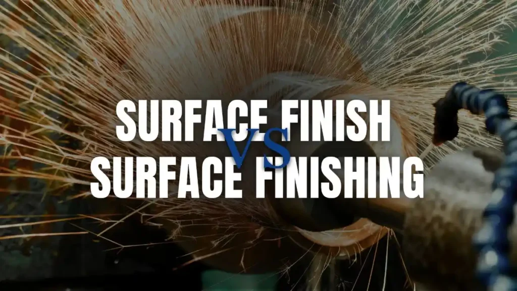
Surface Finish vs. Surface Finishing
Knowing the key differences between surface finish and surface finishing is essential as it helps to make more accurate parts.
Firstly, surface finish is defined as the smoothness or roughness of a part after being cut or shaped. It shows the pure natural texture made during the machining process.
On the other hand, surface finishing is the extra step that is done after the part is made. This can be bead blasting, polishing, coating, or may include other treatments. As a result, it increases the durability and protects against rust.
The key difference is that surface finishing is done during machining, while a surface finishing step is added after that to improve the part.
In industries like aerospace and automotive, both finishing processes are equally essential. They help to make parts look good and fulfill all quality standards.
Key Differences
| Aspect | Surface Finish | Surface Finishing |
| Definition | The resulting texture from machining | Post-machining processes to improve the surface |
| Purpose | Indicates surface quality or roughness | Enhances appearance, durability, or function |
| When it Occurs | During machining | After machining |
| Example | As-machined Ra 3.2 µm | Anodizing, polishing, bead blasting |
| Industry Relevance | Helps ensure dimensional accuracy | Adds corrosion resistance, visual appeal, etc. |
Different Types of Surface Finishes in CNC Machining
When choosing the right surface finish for your machined part, it helps to know how each one affects the cost, look, and use of the part. Below are the most common surface finishes with a brief description of what makes each one different.
1. As-Machined
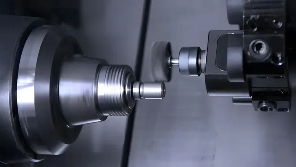
As-Machined Surface Finish
This is the basic finish you get straight from the CNC machine. You can see tool marks, but the part is accurate in size. Good when surface look isn’t important and you want fast and low cost.
2. Smooth Machining
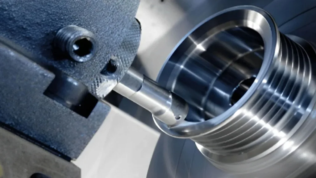
Smooth Machining Surface Finish
One more light cut is added to make the surface smoother. Looks better than the basic finish, but no extra steps. Good when you want a balance between cost and appearance.
3. Bead Blasting
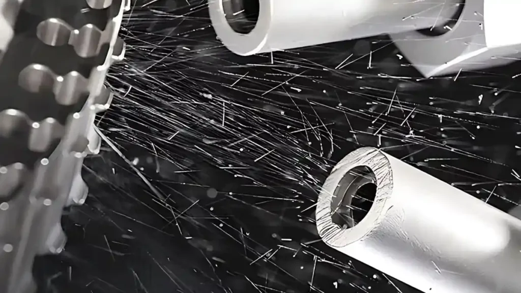
Bead Blasting Surface Treatment
Tiny glass beads are shot at the part to make a smooth, dull surface. The result is an even, clean look. Used for parts that need to look nice but don’t need rust protection.
4. Polishing
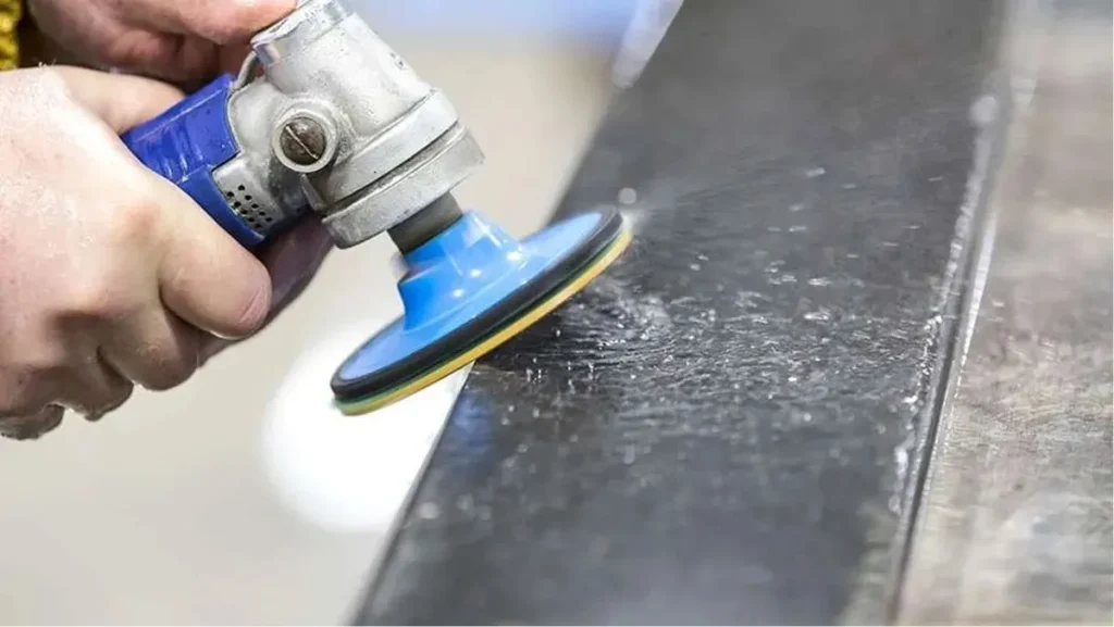
Polishing Metal Surface
This finish uses fine abrasives to remove marks and make the surface shiny like a mirror. Used for medical, optical, or stylish designs where both look and cleanliness matter.
5. Anodizing
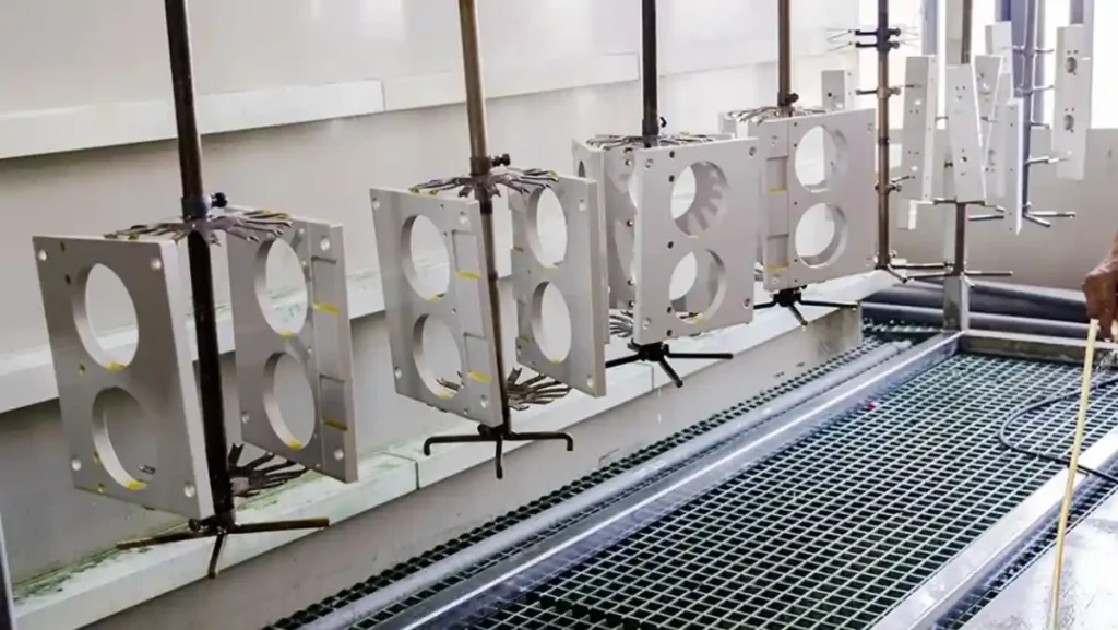
Anodizing Metal Parts
This process adds a layer to aluminum. Stops rust, adds hardness, and can give color. Perfect for outdoor or electronic parts.
6. Powder Coating
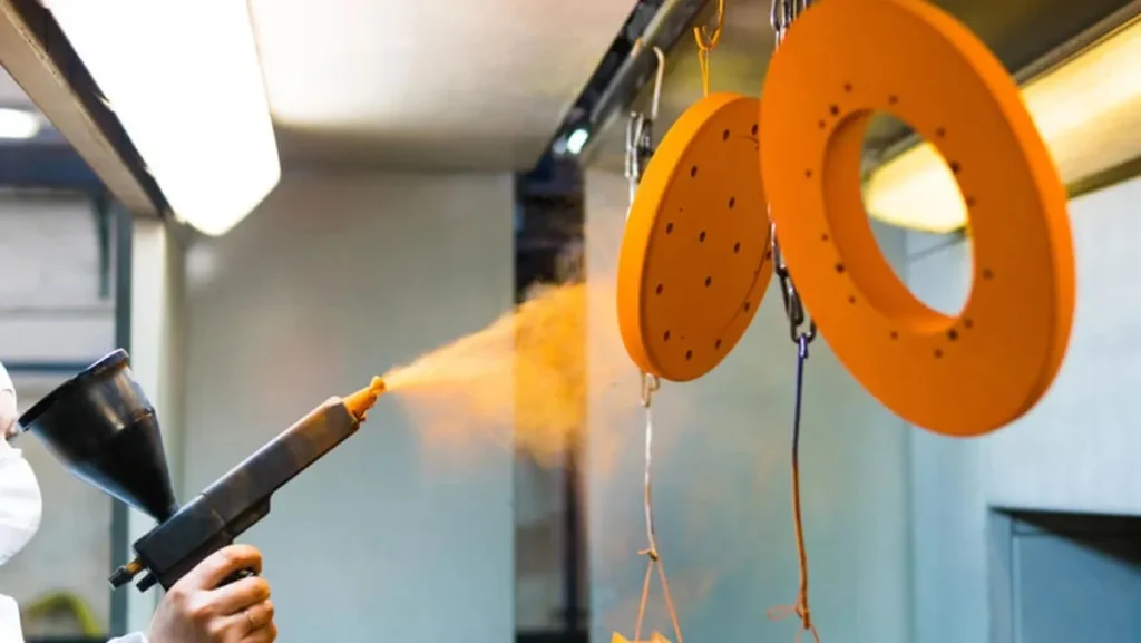
Powder Coating Process
Dry powder is sprayed and baked to stick. Makes a tough, colorful surface that lasts long. Used for tools, machines, or home products.
7. Black Oxide
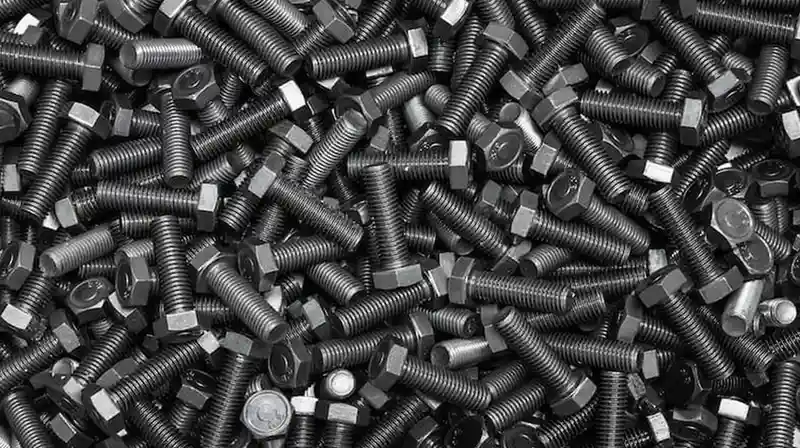
Black Oxide Coating
This chemical finish gives a black color and some rust protection. Doesn’t change the size of the part and works well on steel.
Surface Finish Type Comparison Table
| Surface Finish | Appearance | Durability | Protection | Cost |
| As-Machined | Tool marks visible | Low | None | Very Low |
| Smooth Machining | Slightly shiny | Medium | None | Low |
| Bead Blasting | Matte, uniform | Medium | None | Medium |
| Polishing | Glossy, reflective | High | None | High |
| Anodizing | Colored, smooth | High | Excellent | Medium |
| Powder Coating | Bright, thick coat | Very High | Excellent | High |
| Black Oxide | Matte black | Medium | Moderate | Low |
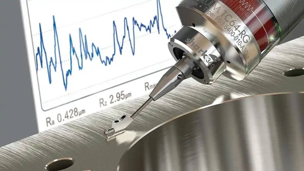
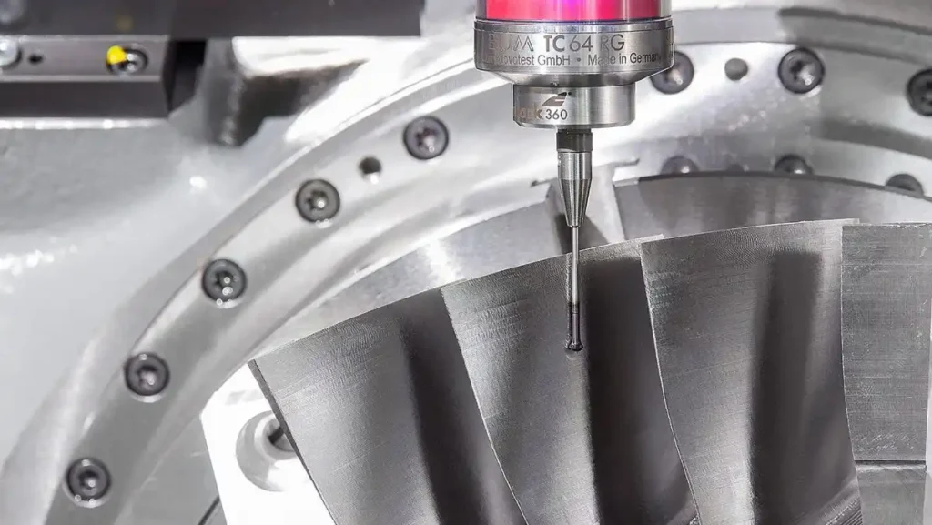
Types of Equipment to Check Surface Finish
Equipment to Check Surface Finish
Here are some easy ways to check how smooth or bumpy a surface feels:
1. Profiling Method
Small tool that goes over the surface to feel how it looks. Just like a music player needle does. This method finds very small details on surfaces. But this way does not work good with big machines.
2. Microscopy Method
Strong looking tools help see the surface very close up. This helps find small marks like tiny hills or holes. These marks are hard to see with just eyes alone.
3. Area-Based Method
Takes one small part of the surface to find how rough it really is. This method uses special tools like sound waves or light beams. This way is easy to use, and machines can do it by themselves many times.
Surface Finish Comparison Chart
Surface finish means how smooth a part feels after making it. It shows the texture on the surface of each part. This finish affects how the part works with other parts. It also affects how long the part will last. Different jobs need different finish standards. These standards help make sure parts work the right way.
The surface finish chart below shows different roughness numbers. It compares Ra, RMS, CLA, Rt, and ISO grade numbers in one place. This chart helps change between different units and standards.
Engineers use this chart to pick the right finish. Machinists use this chart to check their work. Quality checkers use this chart to make sure parts are correct.
| Ra (µm) | Ra (µin) | RMS (µin) | CLA (N) | Rt (µm) | N (ISO Grade) | Cut-off Length (in) |
| 0.025 | 1 | 1.1 | 1 | 0.3 | 1 | 0.003 |
| 0.05 | 2 | 2.2 | 2 | 0.5 | 2 | 0.01 |
| 0.1 | 4 | 4.4 | 4 | 0.8 | 3 | 0.01 |
| 0.2 | 8 | 8.8 | 8 | 1.2 | 4 | 0.01 |
| 0.4 | 16 | 17.6 | 16 | 2.0 | 5 | 0.01 |
| 0.8 | 32 | 32.5 | 32 | 4.0 | 6 | 0.03 |
| 1.6 | 63 | 64.3 | 63 | 8.0 | 7 | 0.03 |
| 3.2 | 125 | 137.5 | 125 | 13 | 8 | 0.1 |
| 6.3 | 250 | 275 | 250 | 25 | 9 | 0.1 |
| 12.5 | 500 | 550 | 500 | 50 | 10 | 0.1 |
| 25.0 | 1000 | 1100 | 1000 | 100 | 11 | 0.3 |
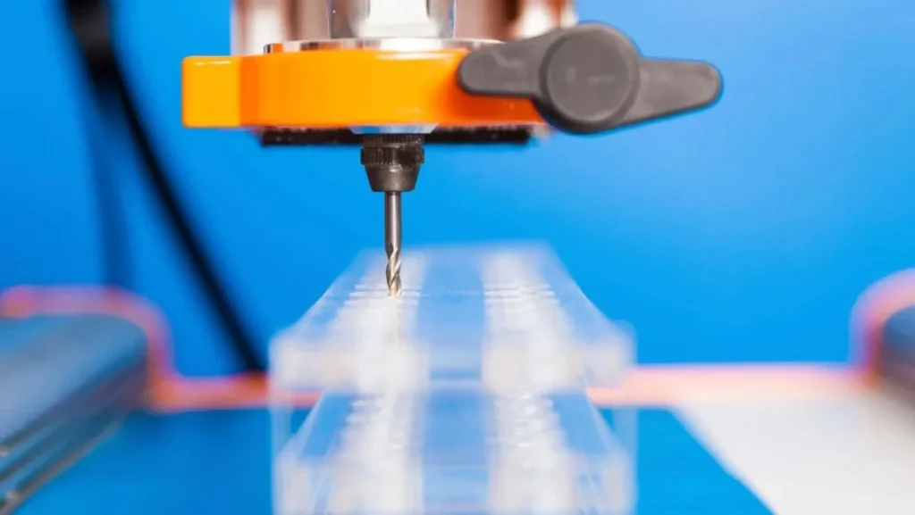
CNC Machining Surface Roughness
CNC machining surface roughness is the tiny pattern or texture left on a part after it’s been cut or shaped by a CNC machine. These small bumps and dips are natural and occur during the cutting process and can affect how the part looks and works.
Surface roughness is measured in micrometres (µm) or microinches. The lower the number, the smoother the surface. This texture is not added later; it’s there from the machining process. Tool sharpness, cutting speed, feed rate, and material used all affect the outcome.
Why does this matter? Surface roughness can affect how well a part seals, resists damage, fits with other parts, and even its final appearance and overall quality.
Moreover, Surface roughness levels change how parts work and fit, and look. This quick chart gives you tiny measurements in different units. It shows typical uses for each finish type, too. You can use machining or grinding, or polishing methods here.
These numbers help you pick the right finish for your job.
| Micrometers (µm) | Microinches (µin) | Applications |
| 25 | 1000 | Clearance areas |
| 12.5 | 500 | Rough machining |
| 6.3 | 250 | General fitting |
| 3.2 | 125 | Heavy load parts |
| 1.6 | 63 | Controlled feed |
| 0.8 | 32 | Precision grind |
| 0.4 | 16 | Smooth finish |
| 0.2 | 8 | Seal surfaces |
| 0.1 | 4 | Gauge work |
| 0.05 – 0.025 | 2 – 1 | Ultra-precision |
Methods to Measure Surface Roughness
Methods to Measure Surface Roughness
Surface roughness means holes on small bumps and surfaces. These small changes affect how parts work and move together. They change how things rub and seal tight spots. RA is the most common way to investigate this. RA shows the average height of these small changes.
Direct measurement: A thin needle moves slowly on the surface area. It touches and detects bumps and holes on the parts. The movement turns into numbers that show the quality of the surface. For metal parts, special equipment examines surfaces without touching them.
Visual Comparison: Part is compared to sample pieces made of identical material. One sees both pieces closely and feels surfaces. They choose the sample that matches the part to the closest. This method works quickly but gives less accurate results than others.
Optical Measurement: In this way it uses light devices such as laser and special microscope. They scan the surfaces without touching them during the check. Some systems use sound waves instead of using light beams. These methods work fast and always give very accurate results.
Real-time monitoring: Some new CNC machines now check the roughness while making parts. This provides problems for machine users and cures them quickly. They do it exactly without stopping the production lines. It helps to keep the same quality during the process of making the whole.
Surface Roughness Charts Symbols
Surface roughness is how smooth or rough the surface of a machined part is. This matters because it affects how the part works, looks, and fits with other parts. Here are some ways to measure surface roughness:
Ra (Roughness Average): This is the average roughness. This is the most common value.
Rz: This is the average height between the highest peaks and lowest valleys in a few test areas.
Rt: This is the total height between the tallest peak and deepest valley over one full length.
RMS: This is like Ra but gives more weight to deeper scratches or bigger bumps.
Symbols such as Ra, Rz, and RMS are used in drawings to indicate the level of roughness. They help manufacturers stick to the right standard.
To simplify, engineers refer to a surface finish chart. This suggests what level of smoothness a part needs based on its function – whether it is for sealing, moving, or appearance.
These values help us check the surface finish measurements if a part is smooth enough for sealing, fitting, or moving parts.
| Indicator | Main Focus | Sensitivity | Common Use |
| Ra | Average surface roughness | Low | General machining, casting, grinding |
| Rz | Peak-to-valley average | Moderate | Seals, wear parts, load-bearing parts |
| Rt | Total height difference | High | Quality checks for defects |
| RMS | Emphasizes bigger deviations | Moderate–High | Optics, precision parts |
Common Surface Roughness Values in CNC Machining
When creating CNC machined parts, the surface smoothness is not by chance—it’s done on purpose. Each part needs a certain type of finish, depending on how it will be used. This smoothness is usually measured in Ra (Roughness Average).
A lower Ra value means a smoother surface, but it also takes more time, effort, and money to achieve. So, it’s important to find a good balance between how the part performs, how much it costs, and what it needs to do.
For instance, a rough finish is okay for parts that don’t need to move or seal tightly. But if the part moves, needs to fit tightly, or handles pressure, a smoother finish is better.
Here’s a simple RA surface roughness chart to help you choose the right finish:
| Ra Value (µm) | Finish Type | Description | Best For |
| 3.2 µm | Standard | Visible tool marks, easy to achieve | General parts, non-critical areas |
| 1.6 µm | Semi-smooth | Moderate smoothness, low cost | Light load parts, better fits |
| 0.8 µm | Fine finish | Minimal tool marks, good precision | Stressed parts, moving components |
| 0.4 µm | Ultra-smooth | Very fine texture, polished look | Sealing surfaces, medical components |
| 0.2 µm | Precision | Mirror-like finish, tight tolerance | Instruments, sealing faces |
| 0.1 µm | Ultra-precision | Exceptional smoothness, high control | Aerospace parts, precision gauges |
To explore and compare values in one place, Check out our: surface finish chart PDF, which provides visual and numeric data for reference in the design and inspection stages.
Surface Roughness Conversion Chart
Surface Roughness Conversion
Knowing surface roughness helps manufacturers check how smooth or rough a part is after it’s been machined. Different industries use different units to measure surface roughness—Ra, RMS, micrometers—though they all describe the same thing.
That’s why engineers use a surface roughness conversion chart to match and compare these values. It helps them choose the right surface finish for how the part should look and work.
Here’s a simple table to compare surface roughness values from different systems:
| Roughness Grade | Ra (µm) | Ra (µin) | RMS (µin) | Common Use |
| N1 | 0.025 | 1 | 1.1 | Precision optics, gauge blocks |
| N4 | 0.2 | 8 | 8.8 | Seals, fine sliding parts |
| N6 | 0.8 | 32 | 35 | Standard mechanical components |
| N8 | 3.2 | 125 | 137 | Structural parts, rough milling |
| N11 | 25 | 1000 | 1100 | Castings, forged surfaces |
| Roughness Grade | Ra (µm) – Metric | Rz (µm) – Metric Range | Ra (µin) – Imperial | Rz (µin) – Imperial Range | Typical Applications |
| N12 | 50 | 156.2 – 272.6 | 2000 | 6249.8 – 10905.7 | Rough castings, flame-cut parts |
| N11 | 25 | 80.9 – 162.1 | 1000 | 3235.1 – 6484.6 | Forged surfaces, general casting |
| N10 | 12.5 | 80.9 – 162.1 | 500 | 1674.6 – 3855.8 | Heavy milling, rough grinding |
| N9 | 8.3 | 21.8 – 57.7 | 250 | 873.4 – 2306.4 | Coarse turning, shaping |
| N8 | 3.2 | 11.5 – 34.7 | 125 | 458.9 – 1387.7 | General machining, structural parts |
| N7 | 1.6 | 5.9 – 20.6 | 63 | 237.6 – 825.1 | Medium finish machining, gears |
| N6 | 0.8 | 3.1 – 12.3 | 32 | 123.0 – 490.6 | Standard mechanical components |
| N5 | 0.4 | 1.6 – 7.3 | 16 | 63.7 – 291.7 | Precision fit parts, sliding components |
| N4 | 0.2 | 0.8 – 4.3 | 8 | 32.9 – 173.5 | Seals, fine sliding mechanisms |
| N3 | 0.1 | 0.4 – 2.6 | 4 | 17.1 – 103.1 | High-precision tools, dies |
| N2 | 0.05 | 0.2 – 1.5 | 2 | 8.8 – 61.3 | Precision optical surfaces |
| N1 | 0.025 | 0.1 – 0.9 | 1 | 4.6 – 36.5 | Gauge blocks, ultra-fine optics |
How to Choose the Right CNC Machining Surface Finish?
Choosing the right surface finish for your CNC part involves a few simple but important things.
First, think about what the part is for. If people will see it, you might want a smooth or shiny finish.
Next, will the part need to be rust or damage-free—some finishes can help with that.
Also, remember some finishes take more time and money, so consider your budget and deadlines.
Don’t forget to consider the material—some finishes are better for aluminum, others for steel.
And finally, if the part needs exact sizes, try to avoid finishes that add thickness.
| Factor | Why It Matters | Best Option Example |
| Appearance | For visible or customer-facing parts | Polishing, Anodizing |
| Corrosion Resistance | To avoid rust or wear | Anodizing, Passivation |
| Cost & Time | Budget and delivery schedules | As-machined, Brushing |
| Material Type | Some finishes only work on certain metals | Anodizing (Aluminum), Black Oxide (Steel) |
| Functionality | Moving parts need low friction | Electropolishing, Grinding |
Conclusion
Understanding the CNC machine’s surface finish is important to create parts that look good, look longer, and perform well. Whether it is a basic cut or a protective coating, each finish plays a role in strength, appearance, and function.
By choosing the right option depending on your requirements and materials, you can improve the quality of the part and reduce issues. ProleanMFG helps businesses choose the right finish for their part’s function, material, and cost.
Get started today with our CNC Machining Services or Request a Custom Quote to turn your product into a high-performance machine.
FAQs
Q1. What is the standard surface finish for machining?
Typically 3.2 µm Ra for standard and 0.4 µm Ra for high precision parts, depending on material and application.
Q2. What are the different types of surface finishes?
Mechanical, chemical, electrochemical, and thermal methods, including bead blasting, anodizing, polishing, and passivation.
Q3. What is RA 0.8 surface finish?
Fine finish is used for sealing surfaces or aesthetic parts that require low friction.
Q4. What is the ISO standard for surface roughness?
ISO 4287 and ISO 1302 are the global standards that define roughness parameters and symbols.