Camshaft machining serves as an essential precision process in the performance of internal combustion engines. Here, through cam motions, the valve motion has to correspond to the allotted timing from the cam.
This technical guide will help you learn in detail about camshaft cutting while dealing with CNC machining, cutting parameters, and feed rates to achieve high-performance camshafts.
This document elucidates the processes, tools, and considerations needed for manufacturing camshafts with proper geometry and a finished surface using engineering principles and industry practices.
What Is Camshaft Milling?
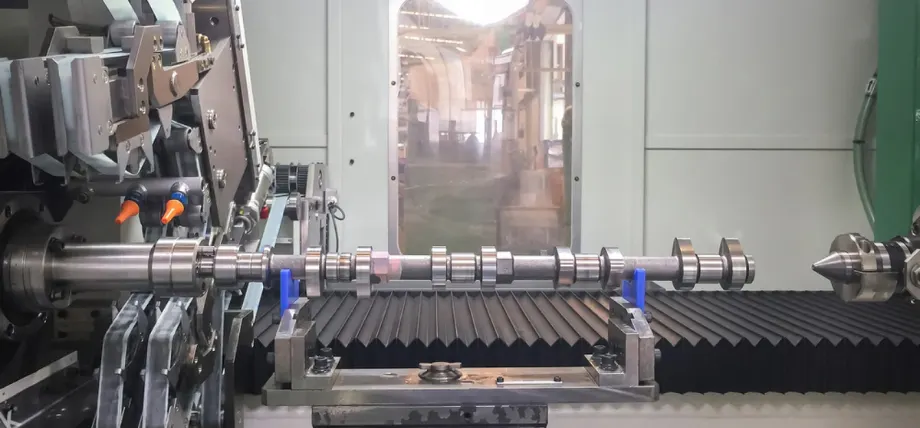
Camshaft machining
Milling a camshaft involves shaping a camshaft blank that is generally made of 8620 steel or cast iron-type material into a working cam with the proper profiles. The primary function of a camshaft is to operate the valve train, with cam lobes determining the valve lift, duration, and timing to fulfill it.
The milling operation uses CNC mill or lathe to rough out the shape of the camshaft, including journals, lobes, and bearing surfaces. The material’s hardness, the tools’ selection, and the machine’s rigidity are important factors to consider to achieve accuracy and increase tool life.
The cutting process starts with the disposal of the cylindrical blank or bar-stock into the lathe’s headstock or the mill’s rotary table.
Using carbide or high-speed steel tooling, the machinist proceeds to rough out the camshaft through the mechanism of the base circle and the preliminary lobe geometry. The radius of the base circle is established early in the process since it is critical to valve timing and must be concentric.
In the case of a high-performance camshaft, such as one made by Comp Cams, the cam profile is held to very close tolerances, which can be checked by using an Adcole measurement system.
CNC Machining of Camshafts
Using CNC machining, camshaft manufacturing can be improved by giving multi-axis operations and control over the toolpath.
The procedures of CNC camshaft machining, including setup, turning, lobe cutting, and grinding, along with associated cutting parameters and feed rates, are described in this section.
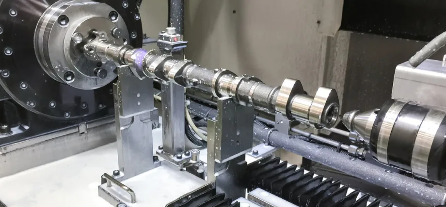
Setup & Workholding
Camshaft workholding
The effectiveness of the setup depends on eliminating vibrations and ensuring accuracy. A camshaft blank is placed between the headstock and tailstock of a CNC lathe or clamped on a rotary table.
Setting up arrangements like turrets or pivot bars is used to accurately position complex camshafts on a rotary table, such as those for multi-cylinder engines. Any workholding must also be rigid to resist tooling forces during the high-rpm operation.
You can use a vernier scale to ensure proper alignment so that the spindle and the workpiece are perfectly concentric. Any deviation from concentricity will be entered into the cam profile.
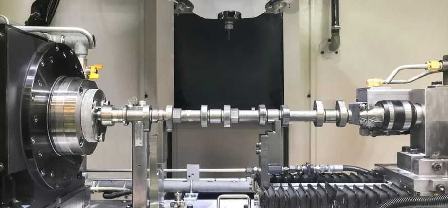
Turning & Rough Machining
Camshaft turning
The turning operations establish the cylindrical features of the camshaft, like journals and the rear end of the camshaft. Normally, a CNC lathe with a carbide insert tool is used for turning at the spindle speed of 800-1200 RPM for 8620 steel, with a feed rate of 0.1-0.2 mm/rev and a depth of cut of 1-2 mm per pass.
Additionally, a coolant is used to cool down the tool and works to evacuate chips, so that the tool life is improved. The rough machining will remove most excess material to form the base circle and journal surfaces vital for the bearing fit and camshaft stability.
Lobe Cutting & Grooving
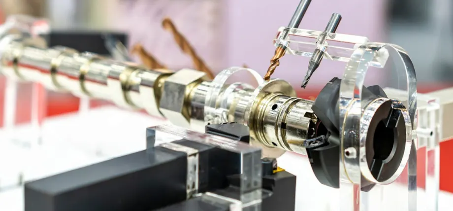
Camshaft drilling pins
Lobe cutting includes shaping the cam lobes to determine valve lift and timing. A CNC mill or specialized cam grinder would use the master cam or programmed toolpath to cut the lobe’s flank and peak.
Typical parameters for 8620 steel are a spindle speed of 1000-1500 RPM, feed rate of 0.05-0.15 mm/rev, and a chip load of 0.01-0.02 mm/tooth. These parameters are for a 4-flute carbide end mill.
Chip load depends upon the number of flutes. Fewer flutes permit higher feed rates for softer materials.
Simultaneous machining of several cams on a single camshaft improves productivity but calls for strict synchronization so that any deflection does not get accentuated.
Precision Grinding & Finishing
Precision grinding cleans the cam lobes to their absolute finish dimensions and smooth surface finish (Ra 0.2-0.4 µm) for maximum lifter interaction.
A cam grinder, with a vitrified aluminum oxide grinding wheel spins at 1500-2000 RPM, feeding 0.02-0.05 mm/rev with a depth of cut of 0.05-0.1 mm per pass.
Induction hardening is commonly performed after grinding to toughen the lobes, and any slight thermal distortions will be corrected by regrinding. A coolant is required to keep the fire at bay. Additionally, the Adcole system checks the lobe geometry after grinding.
For high-performance applications like those designed by Billy Godbold at Comp Cams, the cam profile must achieve tolerances within ±0.01 mm.
Camshaft Machining Considerations
You can manufacture camshafts with fine quality features by solving some technical problems involving vibration control and tool wear, which directly influence cutting parameters and feed rates.
Vibration & Chatter Control
Vibration and chatter often lead to poor surface finish and less-accurate cam profiles. Rigid machine setups with sturdier headstocks and workholding help minimize these problems.
For CNC milling, spindle speed in the range of 1000 to 1500 RPM and a feed rate of 100 to 200 mm/min help to strike an appropriate balance between material removal and platform stability.
The coolant helps suppress heat-generated vibrations, and climb milling is favored when working with non-ferrous materials for a better finish.
Forums such as Practical Machinist and Home Shop Machinist stress the value of a machinist’s skill in tuning the parameters to relevant conditions presented by real-time feedback, for instance, the sound of chatter.
Tool Wear & Feed/Speeds
Tool wear is critical when machining hard materials such as induction-hardened 8620 steel. The preferred tool materials are carbides with high heat resistance, with chip loads of about 0.01-0.03 mm/tooth, meant to reach a compromise between material removal and tool life.
Feed rates depend on material hardness, with softer materials like cast iron permitting higher feed rates (0.1-0.2 mm/rev) compared to harder materials like hardened steel (0.05-0.1 mm/rev).
Spindle speeds must be adjusted to maintain cutting speed (SFM) within 100–150 m/min for steel, calculated as:
Regular tool inspection and adjustment of feed rates, along with consideration of tool geometry prevent excessive wear, ensuring consistent performance across many cams.
Cutting Parameters and Feed Rates
The following table presents typical cutting parameters for camshaft machining using a CNC lathe and a CNC mill with 8620 steel.
| Operation | Tool Type | Spindle Speed (RPM) | Feed Rate (mm/rev) | Depth of Cut (mm) | Chip Load (mm/tooth) |
| Turning (Rough) | Carbide Insert | 800–1200 | 0.1–0.2 | 1–2 | N/A |
| Lobe Cutting | 4-Flute Carbide End Mill | 1000–1500 | 0.05–0.15 | 0.5–1 | 0.01–0.02 |
| Precision Grinding | Aluminum Oxide Wheel | 1500–2000 | 0.02–0.05 | 0.05–0.1 | N/A |
So, the parameters provided act as a first guideline that has to be modified according to the rigidity of the machine, state of tools, and nature of the work material.
Additionally, camshaft machining uses CNC turning (800–1200 RPM, 0.1–0.2 mm/rev, 1–2 mm depth) for journals, lobe cutting (1000–1500 RPM, 0.05–0.15 mm/rev, 0.01–0.02 mm/tooth) for profiles, and grinding (1500–2000 RPM, 0.02–0.05 mm/rev, 0.05–0.1 mm depth) for a 0.2–0.4 µm finish on 8620 steel or cast iron.
For example, if the work material is considered soft, such as cast iron, feed rates can be pushed to 0.3 mm/rev. Much slower feeds and cutting speeds should be employed in extremely hard steels to avoid quick tool damage.
Custom Camshaft Machining Costs
Custom camshaft machining charges depend on material, complexity, and production scale. Manufacturing a single-cylinder cam using a CNC lathe and mill from bar stock is typically charged at $500–$1500 and depends on labor, tool wear, and setup time.
CNC programming and precision grinding steps for race camshafts elevate costs to $2000–$5000 per piece. Induction hardening adds $200–$500, and Adcole verification will cost extra for OEM-grade quality.
Regrinding existing camshafts costs less at $200–$600 since it does not require new blanks. Simultaneous machining reduces the cost per unit for commercial cam production but requires a big investment in multi-axis CNC machines.
Automotive CNC Machining
PROLEANMFG provides high-quality CNC machining for automotive parts and products. Whether you are looking for prototypes or high-volume part production, you can rely on our high-quality CNC cutting services.
Request a free quote today!
Conclusion
Machining camshafts is a complex procedure that requires tight control over cutting parameters, feed rates, and machine setups to manufacture high-performance components. CNC technology can produce camshafts with complex cam profiles efficiently and within exacting valve-train tolerances.
Machinists can minimize vibrations, tool wear, and production cost while maximizing surface finish by optimizing spindle speeds and feed rates coupled with tool selection.
Such technicalities are vital for any son-commercial camshaft, and even more so when you make numerous cams for commercial purposes to ensure the reliability and efficiency of the output performance of engines.