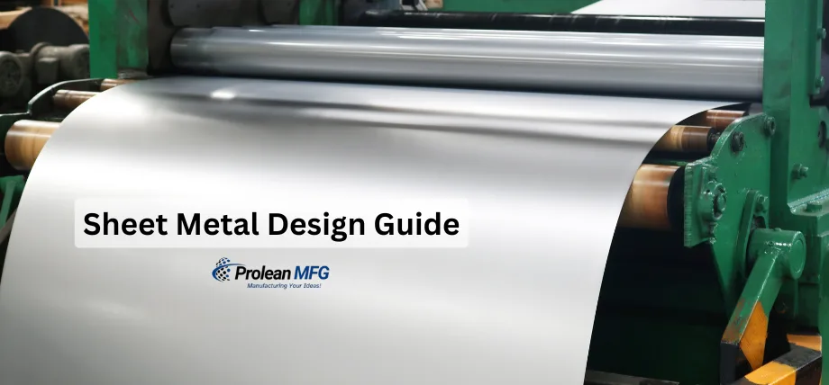

In the realm of mechanical engineering, sheet metal design is a valuable discipline that creates components from thin, flat metal sheets through the processes of cutting, bending, forming, and assembling.
The automotive, electronics, aerospace, and construction industries use this process extensively because it is versatile, cheap, and produces lightweight, high-quality components.
In this guide, you will gain a thorough understanding of sheet metal design principles, processes, and best practices to assist engineers in ensuring parts are functional, cost-efficient, and suitable for production.
Types of Sheet Metal Processes
Sheet metal design
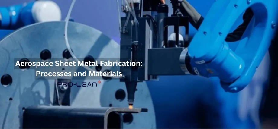
Sheet metal fabrication has a range of processes that are all tailored to specific design requirements and production goals.
The following are key processes commonly used in sheet metal manufacturing:
- Cutting: Material is removed from a sheet for the desired shapes. These include laser cutting, plasma cutting, waterjet cutting, and shearing. Laser cutting is usually preferred for beautiful details and complex geometries, while shearing is best used in straight-line cutting in high-volume production.
- Bending: The sheet is bent along a linear axis to form angles or curves. Usually, press brakes are employed with V-dies and punches to shape the metal. Bending must take into account the characteristics of the material so as not to cause cracking or deformation.
- Forming and Stamping: Forming creates metal shapes by deep drawing or roll forming, etc., whereas stamping uses dies to accomplish features like embossing or perforations. These processes are good for the high-volume production of complex parts.
- Punching: It creates holes or cutouts via a punch and die. CNC turret presses are the most common machines used for high-speed, accurate punching operations.
- Welding and Assembly: Sheet-metal parts need to be joined by welding-type processes (MIG, TIG, or spot) or by mechanical fastening (rivets, screws) to create assemblies. The choice of method depends on material compatibility and structural requirements.
You must ensure that all of these processes perform well and are manufacturable.
Design Principles for Sheet Metal Parts
Here are some key design principles to produce high-quality sheet metal parts.
Material Selection
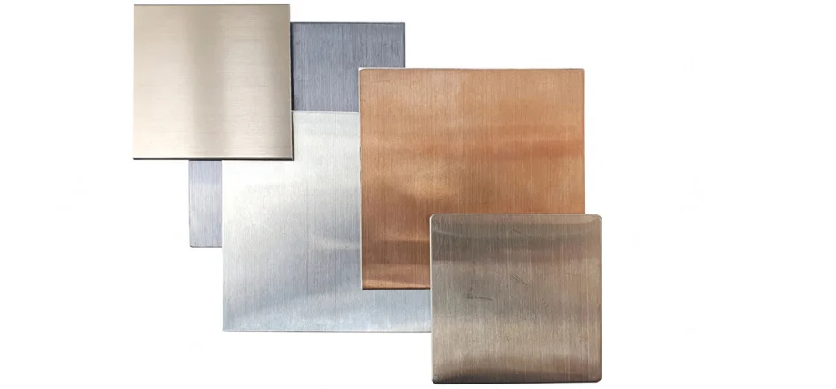
Sheet metal materials
Selecting the appropriate material is important for sheet metal design. Common materials include:
- Steel: Stainless steel and carbon steel are two types of steel that are strong and durable. If you’re working in harsh environments, stainless steel would be the right choice for you because of its corrosion resistance, while carbon steel is cost-effective for structural applications.
- Aluminum: Aerospace and automotive applications usually use aluminum because it is lightweight and corrosion-resistant.
- Copper and Brass: Both of these materials can be used in decoration and electronics because they have good electrical conductivity and aesthetic appeal.
- Titanium: Titanium is expensive, but its corrosion resistance and high strength-to-weight ratio are appealing to aerospace and medical industries.
You must select a material by carefully considering mechanical properties like tensile strength and ductility, along with your budget and environment.
Thickness
Another factor to consider is sheet metal thickness. This is measured in gauges or millimeters, which significantly impacts design and manufacturability. Key considerations include:
- Uniform Thickness: You must ensure that the thickness is uniform across a part so that manufacturing is easier and less costly. Otherwise, multiple processes may be required, making it more complex.
- Structural Requirements: Thicker sheets are strong but heavy and difficult to form, while thinner sheets can be cut easily and are less rigid. You can use FEA to identify the right thickness for load-bearing.
- Process Limitations: Certain processes, such as laser cutting, have maximum thickness limits, while bending requires sufficient thickness to prevent cracking.
You can use standard gauge charts, like those available for steel or aluminum, to help you select the right thickness. For example, automotive panels use a 20 – 22 gauge steel (approximately 1.5 mm).
Design for Manufacturability (DFM)
DFM principles help in ensuring that you can design sheet metal parts so that production is more efficient and inexpensive. Some key guidelines are:
- Minimize Complex Features: You must use simple geometry so that you use a smaller number of operations and tooling requirements.
- Standardize Features: For hole sizes, bend radii, and fasteners, it’s recommended to use already available standards to rely on existing tooling and reduce costs.
- Avoid Tight Tolerances: You must clearly define tolerances that are only as tight as necessary so that you avoid increasing manufacturing costs.
- Consider Tool Access: You must ensure there is seamless clearance for cutting, bending, and forming tools to avoid production issues.
By adhering to DFM principles, designers can reduce lead times, minimize waste, and improve part quality.
Bending Design Guidelines
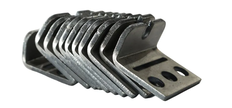
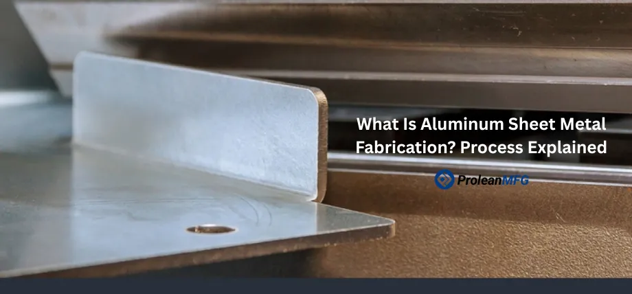
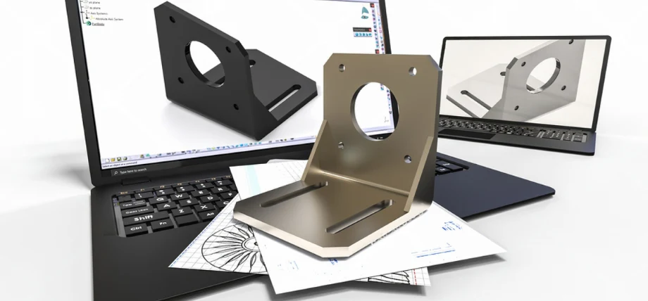
Sheet metal brackets
One of the most important processes in sheet metal fabrication is bending. This is because bending requires careful attention to material properties and tooling constraints. Some guidelines for bending are:
- Bend Radius: You must ensure the bend radius matches the material and temperature. Softer materials may allow 0.5T or 1T, and harder materials can require up to 3T. For example, a 1 mm-thick steel sheet needs to have a minimum bend radius of 1 mm.
- Bend Allowance: Ensure that you calculate the bend allowance for material stretching during bending. This calculation will help you to accurately set the flat-pattern dimensions for cutting.
- Bend Orientation: You must ensure that bends are oriented perpendicular to the material grain to avoid cracking. This is important for high-strength materials like stainless steel.
- Flange Length: The flange lengths must be four times the material thickness so that you can provide sufficient support during bending.
- Avoid Overlapping Bends: Bends must not intersect or overlap, because the material can be distorted, and there may be issues in tooling.
You can use CAD software with sheet metal modules to automate bend calculations and ensure compliance with these guidelines.
Cutting and Shearing Guidelines
The cutting and shearing operations have to be well designed so that clean edges and dimensions can be produced. Guidelines include:
- Minimum Hole Diameter: Punches or cut holes should be no less than 1.0 – 1.5 times thicker than the material used, as it may easily be distorted when punched or cut.
- Edge-Hole Distance: You must follow the distance requirements between holes and sheet edges to avoid distortion. There must be at least 2x material thickness between holes and the immediate edges.
- Kerf Allowance: When laser cutting or plasma cutting, ensure that the kerf (part of the material removed during the cut with the cutting tools) is dimensionally accurate.
- Shear Strength: It is important to choose the shear strength of the material that ensures that the tool is not greatly wasted in the shearing process.
Laser cutting is the method of choice in intricate designs because it is more precise, but in simple volumes of high-volume cutting applications, shearing is appropriate.
Forming and Stamping Considerations
Stamping and forming allow more complex shapes to be generated and stamped; however, they must be well designed in order to prevent defects.
The following are the principal considerations:
- Draft angles: Use draft angles (normally 1 to 2 degrees) of deep-drawn sections to help them easily clear the dies.
- Wall consistency: When forming parts, ensure that there is uniformity in wall thickness to avoid tears or thinning.
- Corner Radii: The radii of the corners should also be as generous as possible so as to reduce the concentration of stress and facilitate the flow of materials during forming.
- Lubrication: State effective lubricants, which will minimize friction and wear during stamping actions.
Stamping is very suitable for high-volume production, where there may be a need to use softer tooling during prototyping to save costs.
Tolerances
Tolerances specify the allowable variation in dimensions and are necessary so that sheet metal parts fit and operate as intended.
Tolerance specification should ideally be a trade-off between the functional requirements and the ability of the manufacturing process, so that you do not pay for something unnecessary.
Processes like laser cutting require close tolerances of ±0.05 mm, allowing them to best serve the needs of the precision component. Shearing works well if employed in high-volume production and offers ±0.25 – 0.5 mm, depending on the machine condition and cut length.
Generally, this process ranks among the more loosely-tolerant processes with ±0.5 mm.
Designers should utilize geometric dimensioning and tolerance to optimize tolerances clearly to communicate requirements and specify only the precision needed for the function.
Overly tight tolerances equate to higher production costs when extra machining, inspection, and possibly rework are added to the production process. For instance, a hole that has to accommodate a loose-fit fastener does not have to be held to the same tolerance standard as one that will be used in a press-fit application.
Tolerance capabilities also greatly depend on such material properties as ductility and thickness, while environmental conditions affecting tolerances include temperature, which can come into play through thermal expansion in large assemblies.
Additionally, it would be ideal to consult with manufacturers during the design phase so that tolerances align with process capabilities, enhancing manufacturability and cost-efficiency.
Design for Prototyping
Prototyping sheet metal parts is a must in design validation before committing to full-scale production. By having prototypes, engineers can check for form, fit, and function and avoid any mishaps during later stages of fabrication.
Soft tooling can be used to increase the cost-effectiveness and timely production of prototypes, with hard tooling being an option for the production of thousands of products.
Prototype geometry is recommended to be as simple as possible, as it ensures that it only consists of the critical features, thereby reducing complexity and cost while providing sufficient means for an evaluation.
During the prototyping phase, it is essential that substitute materials be used that closely approximate the properties of the actual production materials in order to evaluate designs in a cost-efficient manner.
For example, fit and assembly may be tested with a more common alloy, even though the final design requires a grade of stainless steel.
Rapid prototyping means CNC laser cutting or 3D printed fixtures, providing a quick turnaround for reflection and iteration of designs and parts on the basis of test results.
Manufacturer involvement during the prototyping phase ensures that the design can be manufactured, reducing the need for costly redesigns later.
Design Mistakes and How to Avoid Them
Here are some common design mistakes made by designers and tips to avoid them.
Ignoring Minimum Bend Radius
Improper bending with a radius less than the material thickness may result in cracking, breakage, or defect generation.
For example, bending a 1 mm-thick sheet of steel with a radius of less than 1 mm will induce a high-stress concentration near the bend and lead to defects.
As a result, designers should consult the guidelines applicable to the specified material and use CAD tools to verify bend radii throughout the design stage.
Inadequate Edge-to-Hole Distance
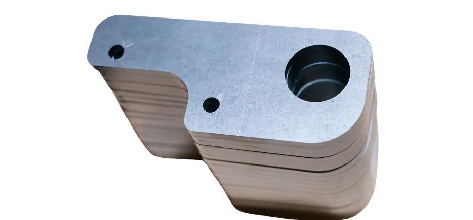
Sheet metal part with edge hole feature
Holes placed too close to sheet edges, well below two times the material thickness, may distort or tear during cutting or forming. For example, a 2 mm-thick sheet requires a minimum hole edge distance of 4 mm.
So, designers should provide ample clearances and verify their designs with manufacturers to ensure that a part is structurally sound.
Overcomplicating Geometries
Designs with complicated geometries, including an excessive number of bends, cutouts, or features, are generally expensive to tool and slow to make.
Designers should consider simplifying the design by reducing the number of operations or using standard features, such as standard hole sizes, to enhance manufacturability.
DFM reviews are good initiatives for designers to identify areas for design simplification without loss of functionality.
Neglecting Material Springback
Springback occurs when a bent piece of material partially returns to its original shape after the removal of the bending force, resulting in dimensional errors. This is quite prominent for high-strength materials such as stainless steel.
A designer should counteract springback using FEA to model and predict it, thereby making compensations by adjusting bend angles or referring to the material data sheets for bend allowances.
Sheet Metal Fabrication at PROLEANMFG
PROLEANMFG offers sheet metal services for everything from bending, forming, and assembly to surface finishes. Our team of engineers follows design guidelines outlined in your technical drawing and DFM principles for high-volume sheet metal production.
Request a quote today!
Conclusion
Sheet metal design is a multifaceted discipline that requires the consideration of material-based properties, manufacturing-based processes, and design-based principles to ensure that both profitable and functional components are created.
Designers will be able to produce strong and durable sheet metal components that can satisfy the needs of a wide variety of industries if they exercise caution to avoid design errors and consult manufacturers during the design phase.