
At ProleanMFG, we use Sheet Metal Bending to fabricate a wide range of sheet metal parts, including brackets, enclosures, cabinets, chassis, and more. On the surface, these components look easy to produce. But in reality, obtaining the right bends takes more than just pressing a sheet into shape.
When metal bends, it stretches. This stretch is enough to affect the final dimensions. Even a small radius change can throw off a design, so precise calculations matter during sheet metal bending.
Common factors influence how much the material elongates. These include:
- The type and thickness of the metal
- The angle and radius of the bend
- The bending method: air bending or bottoming
- The K-factor, also called the neutral or Y-factor
Understanding these details is essential for accurate parts. That’s where our team at ProleanMFG focuses, not just on forming metal but on getting every detail right from the start. Let’s take you through all the intricacies of sheet metal bend radius.
What Is Sheet Metal Bend Radius?
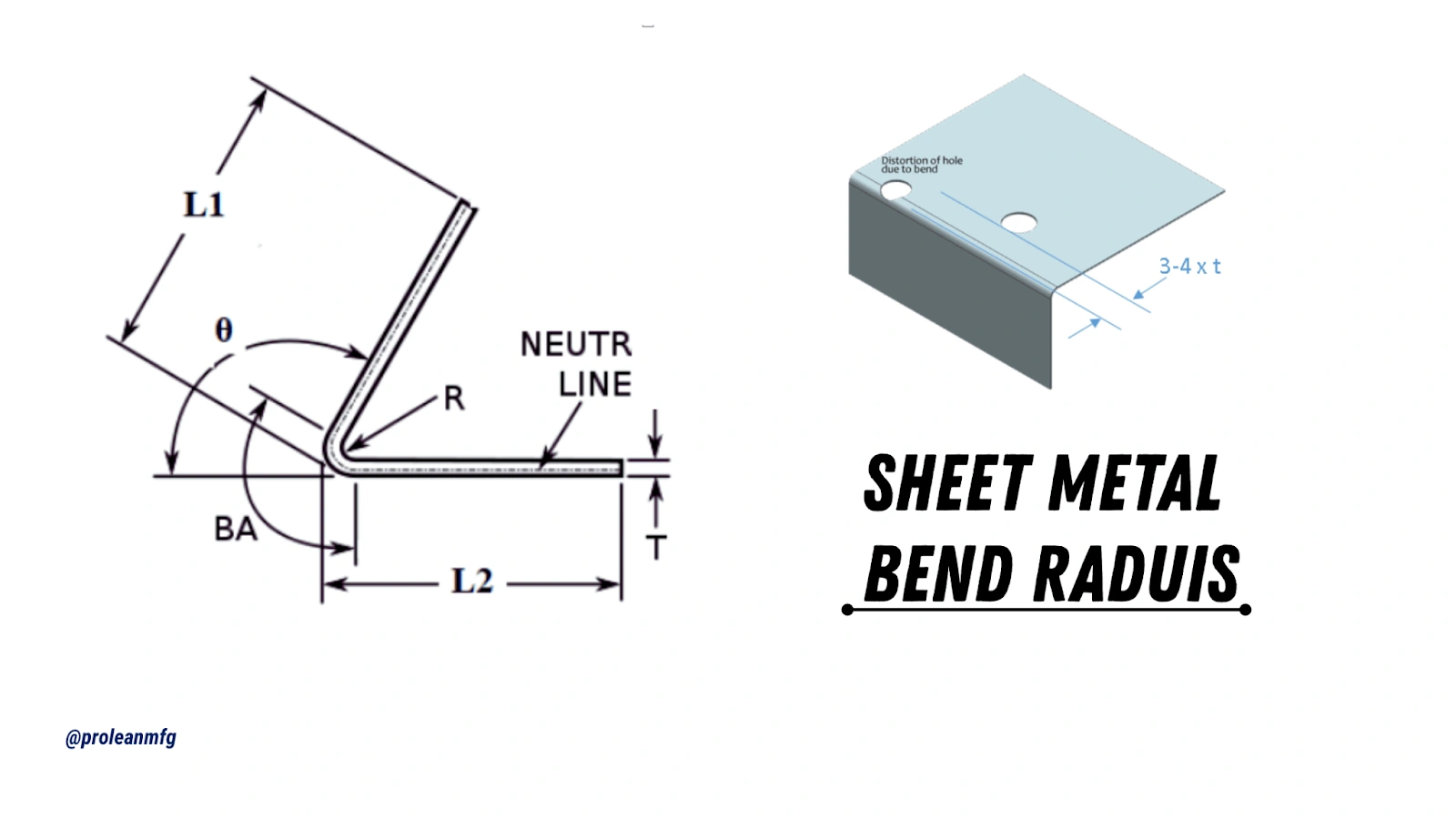
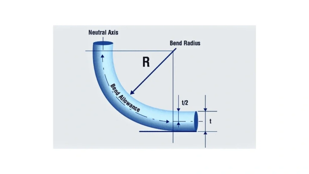
Bend Radius
The bend radius is normally measured between the inside surface of the sheet and the bend center point. It specifies the degree of tightness to which the material can be shaped without damage.
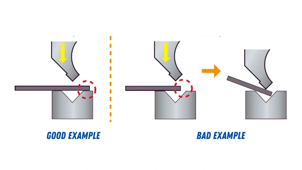
It is imperative to select an appropriate bend radius. If the radius is too small compared to the material thickness, it may lead to cracking or bending distortion. This minimizes the structural strength of the part and exposes it to failure under load.
Common Mistakes in Bend Radius Design
Designing sheet metal requires more than just accurate measurements. There are two frequent mistakes related to bend radius that can slow down production or add extra cost.
Mistake One: Setting a Fixed Radius of 0.100 Inches
The default bend radius for many design platforms, including SOLIDWORKS, is 0.100 inches. Consequently, it usually comes in part drawings. However, this value does not coincide with standard tooling.
The radius of 0.100 inches, in general, requires custom tooling. This is costly and time-consuming. This radius (unless required explicitly by design) must be avoided in favor of regular, tool-compatible ones.
Mistake Two: Matching Radius to Material Thickness
Another common thing is to make the inside bend radius the same as the material thickness. This appears rational, but it causes the same problem as the one mentioned above.
For example, if the material is 0.100-inch aluminum or 0.104-inch stainless steel, the corresponding radius will be 0.100 inches; hence, custom tooling will be necessary.
This is a restrictive method of production that may affect cost-effectiveness. Instead, bend radii should be chosen, conforming to material-dependent guidelines, and the available tooling to simplify production is better.
Factors That Influence Bend Radius
Selecting the correct bend radius is not merely about the shape. It also requires factoring in material behavior, stress distribution, and long-term performance.
Material Thickness & Type
Material properties are key in defining the required bend radius. The more ductile the metal is, the tighter it can be bent without causing damage.
For instance:
- Aluminum is more ductile and has smaller bend radii.
- Stainless and high-strength steel are less forgiving and require wider radii to prevent cracking.
Typical Bend Radius For Different Materials
- Mild steel: bend radius equals 1.5 times material thickness
- Aluminum: For soft aluminum (e.g., 3003-O), the minimum inside bend radius can be as low as 0.5 × thickness. For 6061-T6, it is commonly 1 to 3× thickness, depending on bend orientation.
- Stainless steel: The minimum bend radii typically range from 1× to 2× thickness.
As a general rule, thicker materials demand larger bend radii. Using a too small radius for the thickness can cause material fractures, leading to weak or unusable parts.
Bend Angle
Bend Angle
The bend angle also influences the radius selection. As the angle increases, the stress within the material rises. This may require a larger bend radius to avoid structural damage.
Acute bends are less than 30 degrees, and they focus the stress more severely. Such sharp angles usually increase the chances of cracking, particularly in the harder materials.
In bends more than 90 degrees, larger radii tend to be required to resist issues with material integrity. Where sharp angles are needed, forming techniques like pre-heating or selecting a softer alloy would be suitable.
Springback Effects
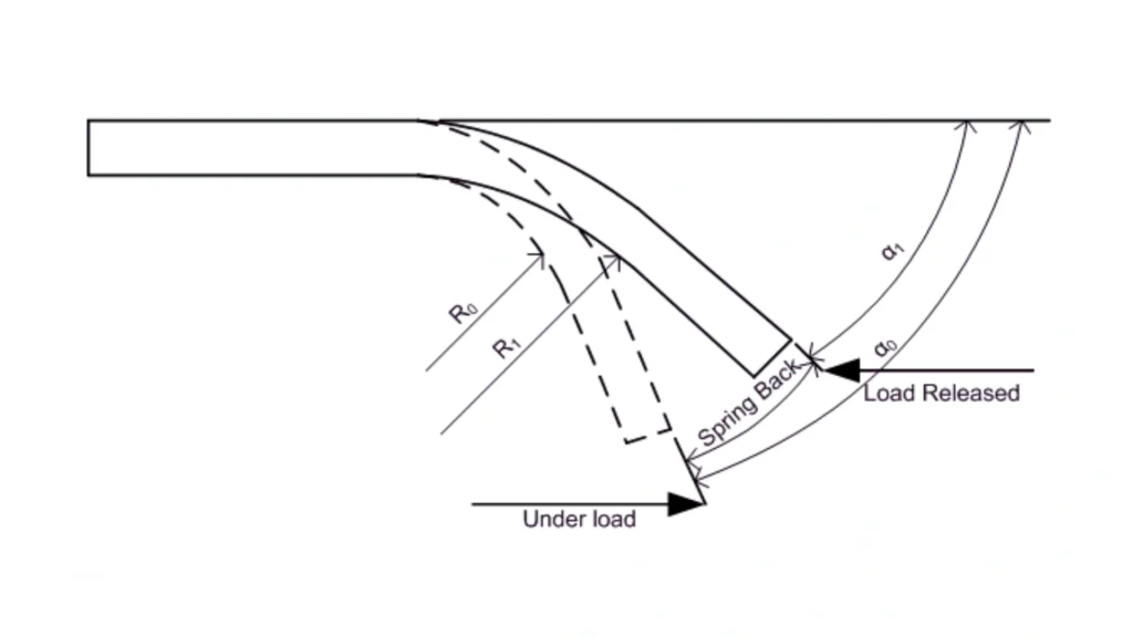
Spring Back In Bending
After forming, metal tends to return slightly to its original shape. Such a behavior is known as springback. This is due to the material’s elastic recovery and must be anticipated in the design phase.
Springback is usually affected by:
- Material hardness
- Bend radius
- Bend angle
The bend radius is often adjusted slightly below the target during forming. To counter these issues, ProleanMFG uses material-specific data and tested bend allowances to ensure the final part matches the required geometry.
Tip: Use bottoming or coining to reduce springback if tighter dimensional control is needed.
Designing for Minimum Bend Dimensions
Minimal Hook and Bend Radius
Tooling limits define minimum bend dimensions. Ignoring them can lead to material warping, cracking, or even part rejection during forming. These constraints are significant when placing features like holes or flanges near a bend.
Understanding how close a cutout or edge can be to a bend ensures that parts can be formed accurately and repeatably using standard equipment.
Minimum Hole Distance
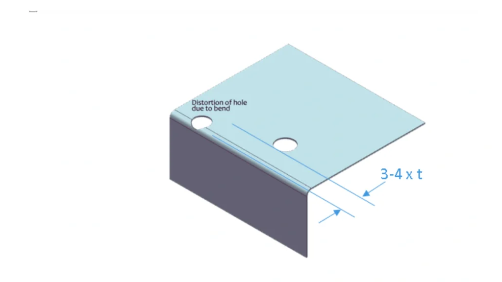
Hole Distortion In Bending
It is the minimum distance from a hole to a bend to avoid deformation during forming. It is applicable in round holes and rounded slots that are oriented at a right angle to the bend line.
The metal can stretch or deform during forming if they are too near. So, check the type of material and the bend radius before hole placement. Design charts usually offer safe minimum values based on standard thicknesses.
As a guideline, keep holes at least 2× material thickness away from the bend line.
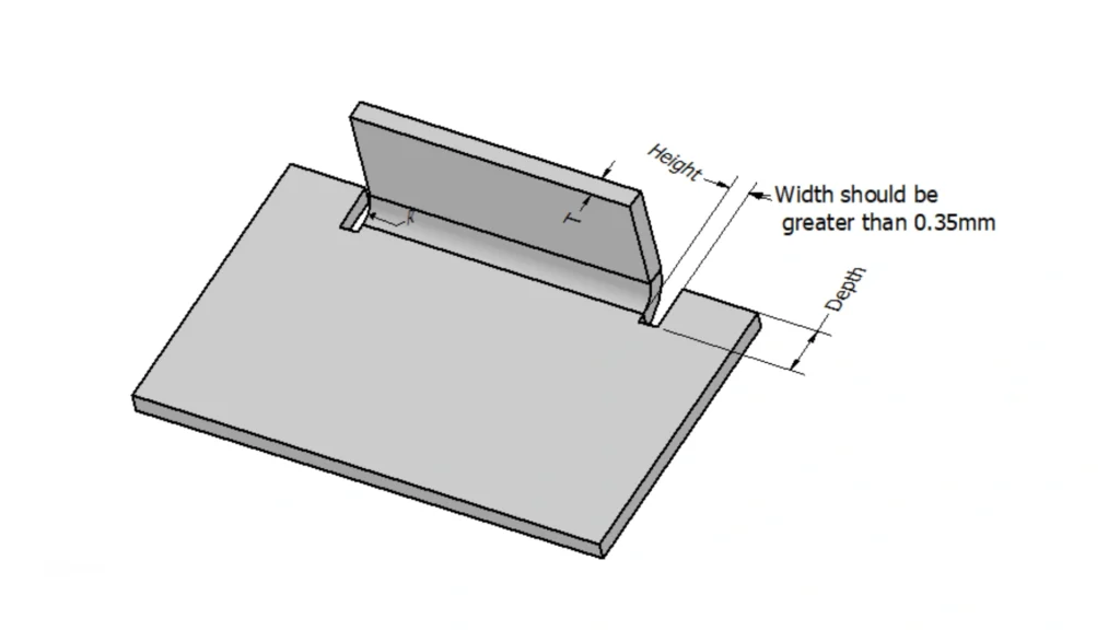
Minimum Flange Length
Minimum Flange Length
The shortest allowable edge is between the start of a bend and the end of a flange or cutout.
This applies to features such as:
- Slots running parallel to the bend
- Rectangular or oval cutouts near the formed edges
A too-short can buckle or tear during bending. Following standard flange length guidelines protects the part quality and supports consistent forming without special tools. For flange length, allow a minimum of 4× material thickness for most materials.
K-Factor and Essential Bending Terms
During custom sheet metal bending, the material stretches and compresses. The K-factor helps you understand why this happens and how to calculate flat layouts accurately.
What Is the K-Factor?
K-Factor Calculation
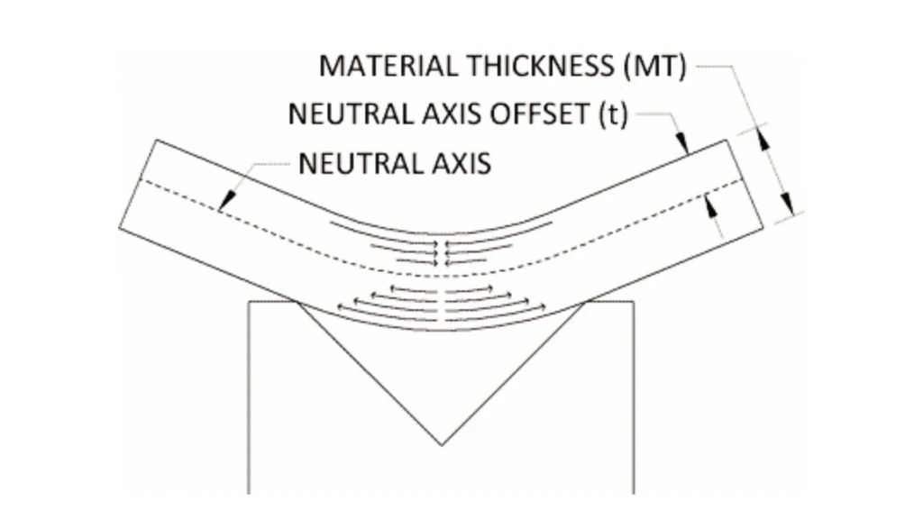
The K-factor determines the position of the neutral axis in the bend. At this axis, the metal neither stretches nor compresses.
- It is a ratio between the neutral axis distance from the inner bend face and the material thickness.
- K-factor value typically ranges from 0.33 for air bends by default. While bottoming often requires 0.42–0.5.
- Harder metals like stainless steel have higher K-factors.
For example, bending a piece of metal is like bending a slice of cheese. The inside compresses, the outside stretches, and the neutral axis lies in between.
You can use the default K-factors provided by CAD software, such as SolidWorks or Fusion 360. These work well for most cases. There is no need to overthink this because manufacturing equipment often uses customized K-factors.
Key Bending Terms You Should Know
OSSB & BA in Bending
Here are a few essential terms to help you design parts that bend accurately.
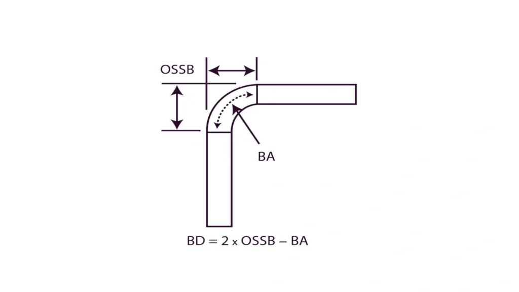
- Outside Setback (OSSB): The distance between the bend’s center and the flange’s outermost edge. To give a bend of 90 degrees, OSSB = Radius of bend + material thickness.
- Bend Allowance: It is the length of the neutral axis of the bend. It tells the extent of the material required to make the bend.
- Bend Deduction: BD is the value subtracted from the sum of both flange lengths to determine the correct flat pattern length
Keep It Simple
Modern CAD and CAM systems calculate these values automatically. You only need to set your material, thickness, and bend radius. Export your design file, and the system handles the rest. So, focus on your design requirements. Leave the detailed bend calculations to the software and manufacturers.
Other Important Sheet Metal Design Considerations
Some standard rules assist in designing sheet metal components to help validate that everything is of good quality and built easily. Considering the thickness of materials, bend radii, and corners will save you time and money on production. However, there are some other factors to consider. For example:
Consistent Material Thickness Is Essential
Sheet metal parts should possess a standard material thickness throughout. You cannot design thickness variations in a component because all components begin with flat sheets.
One part cannot be thick by 1.6 millimeters in one section and thin by 0.8 millimeters in another. The uniform thickness will provide predictable bending and avoid many manufacturing issues.
Selecting Appropriate Internal Bend Radii
Optimal Inside Radius Example
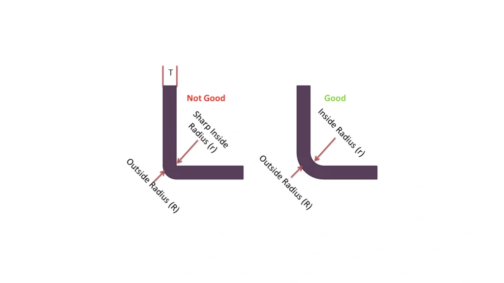
The bend radius formed by the punch itself is internal and influences essential parameters like the K-factor and bend allowance. The selection of an appropriate radius is the main parameter in avoiding cracks and part integrity.
A common rule of thumb is to size the bend relief width equal to the material thickness and the depth at least 1.5× times the thickness. Not all alloys, however, Brittle alloys like 6061-T6 require larger inside bend radii—often 2× or more the thickness, to prevent cracking during forming.
A special radius can be specified, e.g, to accommodate mating components, or to enable sharp internal corners. The radius usually comes in 0.25 to 6.35 millimeters set increments for standard tooling.
Make sure to indicate the selected radius uniformly on each of the part’s flanges. Variations in radii add to the setup of tools and increase production expenses.
Planning for Bend Relief at Corners
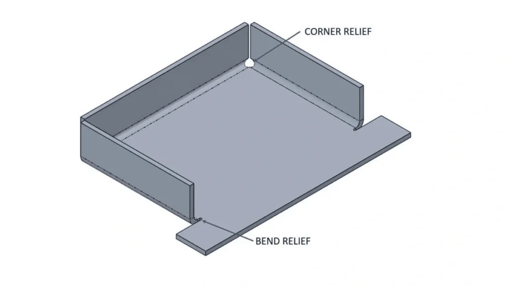
Bend Relief at Corners
As two flanges come closer, it is essential to add bend relief here. These are fine notches, usually 0.76 millimeters in width. These help avert buckling or tearing of material at joints.
Bend relief features in CAD systems are created automatically by many systems. Otherwise, the fabricators will tack them on when they are processing them and notify you when approving the design.
Proleanmfg: Your Partner in Precision Sheet Metal Design
At ProleanMFG, we carefully review your designs to ensure the bend radius is optimal. If adjustments are needed, we make them transparent. Our Engineering team will evaluate and modify unreasonable designs to improve production efficiency and reduce costs. If changes are needed, we let customers know in advance. It helps them avoid unnecessary costs and optimize their design for maximum benefits during production.
If you have any questions about bend radii or other design aspects, our experts are here to help. Choose us for your next sheet metal bending project. Request a quote today, and let’s get started.