
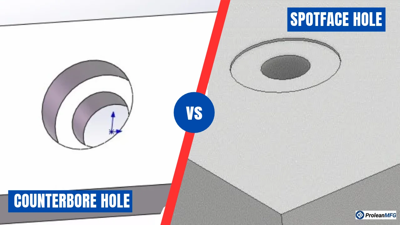

Counterbore and spot face holes are important engineering holes that prevent snagging, loosening, and uneven clamping. But they are distinct in form and function. A counterbore is a cylindrical, flat-bottomed recess sunk into a material to accommodate a fastener’s head flush or below the surface.
A spot face hole is a shallower recess that gives the washer or head of a fastener a flat seat. Both counterbores and spotfaces are machined around drilled holes and form a perpendicular seating area.
Choosing the right feature is important for alignment and clamping, and to prevent fastener interference in assemblies.
Next, we review the counterbore vs spotface question: How they work, their callouts, and applications.
Key Takeaways
- The main difference between counterbore vs spotface is in depth and function. A counterbore recesses the entire fastener head flush and is 3mm to 25mm deep. Spotface is 0.5mm to 2mm deep and only provides a flat seat for the washer or fastener.
- Both the counterbore and spotface holes share the ⌴ symbol, so the callout must be read carefully
- Flatness and hole axis squareness are important requirements for both counterbore and spotface holes.
- Use counterbore for mating and sliding components, and spotface for thin parts and flat surfaces.
What Is A Counterbore Hole?
Two features define a counterbore hole: A small pilot hole and a coaxially machined flat-bottomed recess. This recess is the counterbore.
Important technicalities to note about the counterbore hole are;
- The counterbore depth recesses the entire fastener head
- Depth is typically between 1.8mm and 65.5mm for socket cap head fasteners (ISO 4762) [1]
- The counterbore diameter is larger than the fastener head for clearance.
- Requires Ra 3.2μm surface finish
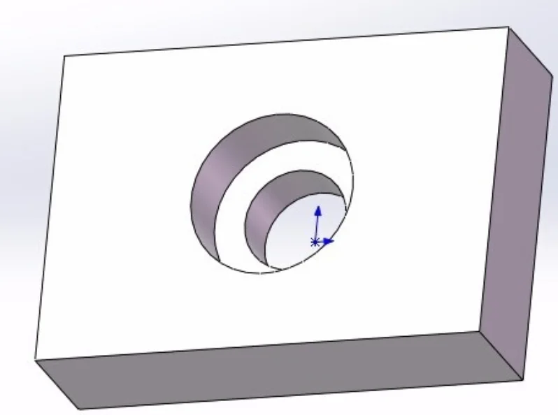
The counterbore hole is designed to allow the fastener to either fall below the surface or be flush with it. The bottom of the counterbore is flat, and the sidewalls are perpendicular to the surface.
Counter Bore Symbol – How To Read Counterbores in Engineering Drawings
A counter bore symbol is symbolized as ⌴. This is the ANSI/ISO standard symbol for a counterbore. In a drawing, the symbol will normally be accompanied by counterbore depth (H), pilot hole diameter (D1), and counterbore diameter (D2).
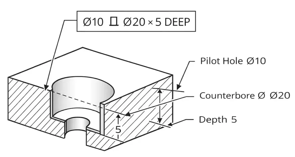
A typical callout for a counterbore looks like ⌀10 ⌴ ⌀20 ⌴ 5 DEEP – shown in the image above. It means that a through hole 10 mm in diameter is drilled. A counterbore hole 20 mm in diameter and 5 mm deep is produced on top of the through hole.
What are the Advantages of a Counterbore?
A counterbore hole offers a flush or sunken head, head protection, concentric location, and a flat bearing seat.
Flush or Sunken Head – The component surface is clear for sliding components and mating parts
Head Protection – The head is protected from wear and impact
Concentric Location – The fastener is centered along the pilot hole
Flat Bearing Seat – The clamp load is spread evenly so the head doesn’t tilt
What are the Limitations of a Counterbore?
Counterbores add machining cost, reduce part strength, demand tight process control, and have head-type restrictions.
Machining Cost – Recessing and drilling processes
Reduced Part Strength – Thin walls can collapse under torque
Tight Process Control – There has to be a balance between a shallow recess that leaves the head popping out and a deep recess that wastes strength
Head-type Restrictions – Countersink holes are preferred for oval heads
What is Spot Facing?
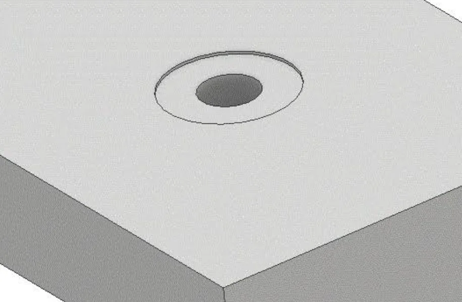
A spot face hole is a shallow recess with a flat bottom machined around a hole to provide a smooth, flat bearing for a bolt head, nut, or washer. Unlike a counterbore, a spotface is just recessed enough to provide a flat reference plane.
An end mill or any other spot face tool machines only enough material to create the spot face hole.
How Deep Should a Spotface Be?
The typical depth for a spotface is between 0.5mm and 2mm. This is just enough to provide a flat landing seat for the fastener and clean up the component surface.
Important features of a spotface hole;
- Depth usually between 0.5mm and 2mm
- Surface flatness control is more important than depth tolerances
- Requires a 3.2μm surface finish
How to Callout Spotface? Spotface Hole Symbol and Callout Example
The spotface symbol is similar to the ⌴ counter bore symbol, but it is followed by the initials SF or SFACE.
An example of a callout of a spotface hole is ⌀15 THRU ⌴ ⌀30 SF. It means a 30mm spotface machined around a 15mm through hole. Sometimes, the depth is not indicated. This implies the spotface depth is just large enough to offer a flat seat for the fastener or neaten the surface.
What are the Advantages of a Spotface?
Notable advantages of spotface are lower cost, minimal material loss, surface cleanup, and square seating for the fastener.
- Lower Cost – The recess is shallow, so the spot face tool only requires minimal spot face machining
- Minimal Material Loss – The shallow depth means less material is lost compared to a counterbore hole
- Surface Cleanup – Creates a smooth landing for the fastener by removing rough surface for forged or cast parts
- Square Seating – The fastener head is perpendicular to the axis so the load is evenly distributed.
What are the Limitations of a Spotface?
A spotface is limited in alignment, concealing the fastener head, flush mounting, and flatness requirements.
Alignment – The fastener can be slightly off-center because there is no sidewall for guidance
Concealing the fastener’s head – The head of the fastener is typically left exposed because the hole is shallow. This exposes the head to wear.
Flush mounting – At a depth of up to 2mm, the spotface does not usually allow for flush mounting.
Flatness Requirement – The hole axis and the seat should be square to each other to prevent head tilting.
Counterbore vs Spotface: What is the Major Difference Between Counterboring and Spot Facing?
Counterboring and spotfacing differ in their engineering symbol, function, depth, surface finish, application, and tools. Of these, depth and function are the clearest distinctions between the two hole types.
The table below summarizes the counterbore vs spotface in machining.
| Element | Counterboring | Spotfacing | Remarks |
| Engineering symbol | Counter bore symbol (⌴), diameter, depth | Spotface symbol (⌴), with SF or SFACE | The additional letters for spot face symbol inform the machinist that a spot face is required |
| Function | Fastener head recessing | Flat bearing seat | The spotface merely squares up the fastener seat while the counterbore hides the head |
| Depth | 3mm to 25mm | 0.5mm to 2mm | The counterbore hole is noticeably deeper than the spotface hole |
| Surface finish | Ra 3.2μm | Ra 3.2μm | Typically, similar surface finish requirements |
| Application | Flush assemblies | Bolts, nuts, and washers for forgings and castings | Counterbore hole – choose when surface must be clear Spot face hole – For rough or uneven surfaces |
| Tools | Counterbore cutter, end mill | Spot face tool (spotface cutter), end mill, back-spotfacing tool | Consider tool geometry, tool material, and other factors as well. |
When to Use Spotface vs Counterbore?
Base this decision on material thickness, surface condition, cost, and head clearance. Use a spot face hole when you only need a flat, square seat for the fastener head. Otherwise, use a counterbore to hide the head.
When Should Counterbore Be Used?
Use a counterbore hole for the following scenarios;
- Where components or features slide past each other, for instance, machine fixtures and bases
- Mating parts that must seat flat against each other – covers and flanges
- Brackets and hinges – no snag allowable on the surfaces
When Should Spotface Be Used?
Use a spotface hole in these situations;
- Uneven bosses on forged brackets and cast housings
- Thin plates or sheets that cannot accommodate deep recesses
- Structural plates and pipe flanges – for local cleaning
What is Reverse Spotface and Counterbore?
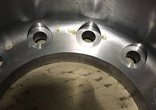
A reverse spotface or counterbore is a cylindrical recess on the rear or hidden side of the workpiece. Machining it normally is difficult because it is inaccessible.
The pilot hole accommodates the spot facing or counterboring tool shank. The cutter is fixed on the far side. The tool retracts when the recess has been cut.
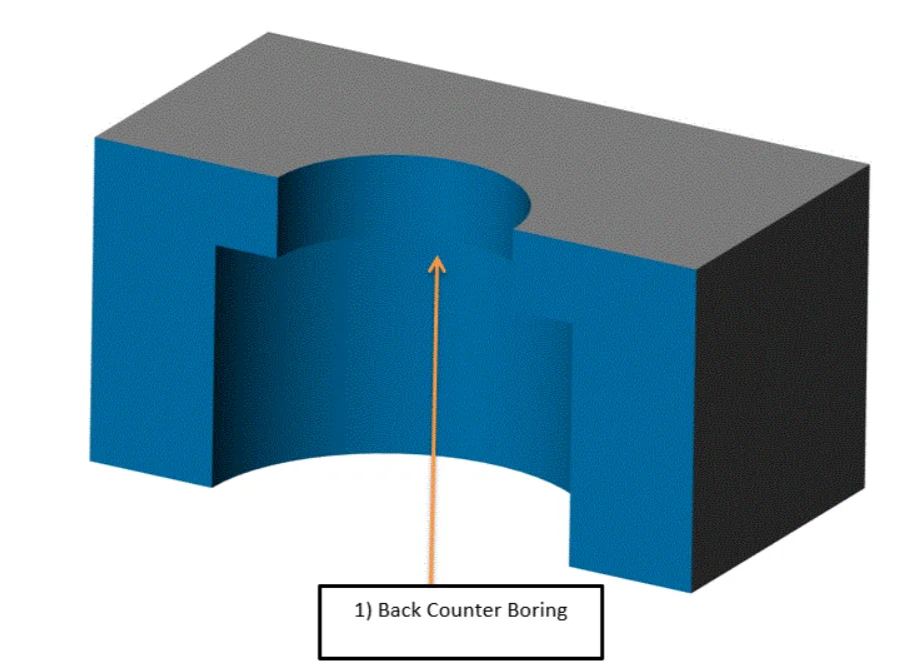
Reverse spotface and counterbore machining is common in blind assemblies and enclosed housings.
Other Types of Engineering Holes in Machining
Apart from spotface and counterbore holes, other engineering holes include blind, through, tapping, tapered, and countersunk holes. Each has specific geometric requirements, communicated through callouts.
Here is a table summarizing some of the other types of engineering holes in machining.
| Engineering Hole Type | Distinctive Geometry | Common Purpose | Example Drawing Callout |
| Blind hole | Defined depth; does not pass through material end to end | Hole that does not break to the opposite end | Ø5 × 10 DEEP |
| Bored hole | Accurate cylindrical hole | Precise alignment, geometry, and diameter | Ø20 H7 |
| Clearance hole | Diameter larger than fastener nominal diameter | Free passage of bolt or screw | Ø15 THRU |
| Countersunk hole | Hole entrance has a conical recess | Flush seating for flathead fastener | Ø10 THRU, C’SINK Ø15 × 90° |
| Dowel-pin hole | Cylindrical hole | Alignment and location of mating components | Ø8 H7 × 20 DEEP |
| Reamed hole | Cylindrical hole – precisely sized and finished | Quality surface finish and accurate diameter | Ø10 H7 |
| Relief hole | Small hole at feature intersection or groove corner | Interference prevention and relief provision | Ø4 THRU |
| Tapped hole | Internal threads | Used with threaded fastener | M8 × 1.25 × 15 DEEP |
| Tapered hole | Hole diameter varies | For tapered interfaces and components | Ø20–Ø16, 1:10 TAPER |
| Through hole | Completely passes through the workpiece | Passage of fluids, fasteners, shafts, pins | Ø15 THRU |
In Conclusion
Counterbore and spotface holes may seem small, but they are critical in mechanical systems and assemblies. Designers use these features to improve the seating quality of fasteners and promote flushness.
But in the counterbore vs spotface comparison, the holes have different designs and applications. By understanding these differences, reading callouts correctly, and noting where to use the features, you will steer away from many assembly issues where holed fasteners are concerned.
If you are looking for precise counterbores and spotfaces promptly, the answer is in our friendly CNC machining services. Upload your CAD drawings today for a quote within 24 hours and, consequently, professional service delivery.
Resources