
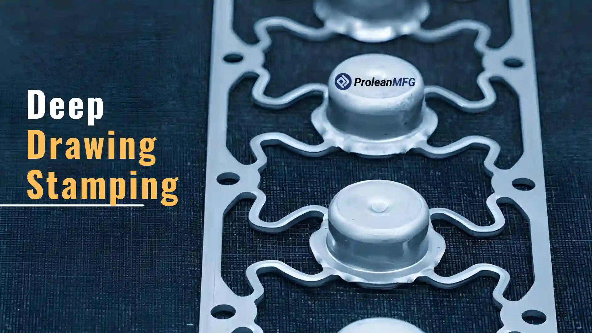

Deep drawing stamping is a sheet metal forming process used to shape flat sheet metal into hollow or three-dimensional parts. It is commonly used when the part depth is greater than its diameter.
The process works by pulling a sheet into a die using a punch, allowing the material to flow and take the required shape. It is widely used for making seamless parts with consistent thickness and good dimensional control.
Deep drawing is a metal stamping process typically performed at room temperature. It is used across industries for producing parts ranging from small components to large structural panels.
The desired outcomes of deep draw stamping depend primarily on the controlled material flow during forming. Factors like die design, material type, lubrication, and clearance all affect how the metal moves during the process.
This article explains how deep draw stamping works, the key factors that affect the process, and where it is commonly used in manufacturing.
Deep Draw Metal Stamping: Definition, Basics, and Importance
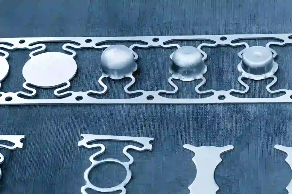
Deep draw forming is a method for producing 3D shapes from flat stock. Metal is pulled through a punch with a die (which gives the desired shape) to create an empty shell.
A “deep draw” occurs when the part’s length exceeds its width. Unlike cutting techniques that remove excess stock, sheet metal can be bent without breaking, creating a completely sealed product with no seams.
A typical setup involves three components: a punch to pull the sheet into the die and a blank holder that controls how the sheet moves into the die.
Punch-to-die clearances are typically about 10% greater than the sheet thickness, providing enough room for easy deformation without overstressing the metal.
Common metals used for this process include low-carbon steel, stainless steel, aluminum, and brass. These selections depend on the required stretch and the tensile strength of the completed component.
Controlled Material Flow and Draw Ratio
Material flow is the biggest challenge in deep drawing metal stamping. Material must deform smoothly without tearing or wrinkling.
One key aspect of controlling material flow is selecting a proper draw ratio. Typically, a good initial draw ratio is 1.8 to 2.2 for the first draw.
Based on the specific properties of each material, blank holder pressure must then be controlled to achieve this ratio. Blank holder pressure must be sufficient to prevent tearing and yet loose enough to avoid flange wrinkling.
Formation of Deep and Seamless Parts
Sheet metal parts made by deep drawing have no welds or joints because they form a single unit. Because the entire unit has been uniformly stretched, parts produced by deep drawing exhibit superior mechanical properties compared to those produced by welding or other forms of assembly.
Parts such as cylindrical housings, containers, and enclosures require both a seamless outer surface and a uniform inner shape. While wall thickness remains relatively constant, some local thinning does occur at highly stressed points – particularly in areas adjacent to sharp angles and punch radii.
Dimensional Control and Repeatability
Deep drawing produces identical parts after the initial die and processing conditions have been established. Tolerancing is limited by both the precision of the dies themselves and material behavior.
Provided that a controlled environment exists, tolerance variability should be within ±0.1mm to ±0.25mm, depending on part size and complexity.
Because it can produce identically dimensioned parts repeatedly with minimal need for secondary machining, deep drawing is ideal for mass-produced products that must be assembled without interference fits.
Material Utilization and Process Efficiency
Compared to conventional cutting methods, most of the stock used for sheet metal blanks can be deep-drawn into finished products. This further increases stock usage efficiency when optimized blank sizes are applied during design.
Additionally, lubricants are often used to reduce friction, improve surface finishes, and extend tool longevity.
Suitability for High-Volume Production
Production utilizing presses becomes extremely productive once all necessary tooling has been developed. In addition to providing a finished or nearly finished part per press stroke, cycle times are primarily determined by both material type and part depth.
For these advantages, deep drawing is suited to applications involving large quantities of consistently manufactured products.
Key Components and Process Factors in Deep Drawing
Drawing deep drawing is controlled by both tooling elements and process parameters. The quality of the final part will be based on how well these two factors manage material flow during forming.
In addition to core tooling such as Punch and die, other variables, such as pressure, lubricant use, and geometry, directly impact whether the part will properly form and fail during this process.
Material Selection and Formability
Material selection significantly affects how sheet metal behaves during forming. The materials most frequently used for forming are those that elongate without cracking.
Low-carbon steel, stainless steel, aluminium, and brass are among the most common metals used in forming applications.
The two key characteristics most often analyzed are the n-value (strain-hardening exponent) and the r-value (plastic strain ratio).
- n-value: The n-value is an indicator of how well a material can be stretched.
- r-value: The r-value indicates how resistant the material is to thinning.
Thicker sheets are generally easier to control during the forming process because they offer greater stability. Additionally, they can withstand greater deformation before failing than their thinner counterparts.
Punch, Die, and Die Clearance
The punch and die are the fundamental elements of the tooling system used to develop the desired geometry in the formed part. The Punch pushes the sheet into the die opening. The die develops the final geometry.
Typically, the clearance between the Punch and die is set slightly larger than the sheet thickness to facilitate the passage of the material.
Too little clearance generates excessive friction, potentially leading to material tears. Too much clearance reduces dimensional accuracy. Also, the die entry radius affects material flow.
A smaller radius limits material flow and increases the risk of fracturing, whereas a larger radius increases the risk of wrinkling when working with thin-gauge sheet stock.
Blank Holder and Binder Pressure
The blank holder controls how the sheet metal flows into the die during forming. Adequate pressure is necessary to balance retaining the material’s position with providing sufficient allowance for its movement.
Should pressure be inadequate, there is a risk of wrinkles forming due to uncontrolled material flow.
Conversely, if adequate pressure is applied, it may restrict material flow, thereby causing tears. Practical setups adjust binder pressure according to sheet metal type and thickness.
Stand-offs are used in many cases to provide a controlled gap (typically about 110% of sheet metal thickness) to allow free-flowing material without being subjected to excessive compressive forces.
Draw Ratio and Blank Size
The draw ratio relates to the amount of material deformation in a single operation. It is determined by comparing the blank size relative to the punch size. Should this ratio exceed the maximum allowable value for a given material type, then the material cannot flow effectively and may rupture during forming.
When producing deep-drawn parts, multiple drawing processes are normally utilized. During each subsequent draw, only the reshaping of pre-existing material occurs. Therefore, sufficient material should be available to establish the ultimate configuration in initial drawings.
An optimized blank size and shape will enhance forming stability, as an oversized blank increases compression forces and inhibits material flow. Conversely, a properly designed blank will promote improved forming stability.
Lubrication and Surface Finish
The friction generated between sheet metal and tooling influences how easily sheet metal moves past tooling. Lubricants are applied to reduce friction, thereby enhancing smooth flow into the die.
Additionally, lubricant application enhances surface finishes of formed products by reducing friction-generated wear on tooling surfaces. Tooling surfaces are generally polished parallel to the direction of material flow to further reduce friction.
Poorly lubricated surfaces or poorly finished tooling surfaces generate increased friction, which may cause either tearing or irregularities in formed products.
Press Force and Speed (Ram Control)
The press equipment is responsible for developing the force needed to pull the material into the desired configuration. Press force must correspond to the material strength, material thickness, and the product configuration being developed.
Similarly important is press speed, as it allows the material sufficient time to flow appropriately. If excessive speeds are used, the material will not deform uniformly, resulting in imperfections.
Providing a consistent means of managing pressing operations will help maintain consistency across parts produced using this method.
Draw Beads and Flow Control Features
Draw beads are used to control material flow entering dies by creating restrictions in specified areas. As material encounters these Features during forming, it undergoes deflection, followed by straightening, which helps regulate flow.
Flow regulation is particularly beneficial when dealing with complex geometries where the distribution of material must be balanced.
Adjusting the draw bead height and/or shape enables operators to control the amount of restraint applied during forming operations, thereby preventing undesirable effects such as wrinkling or non-uniform wall thickness.
Part Geometry and Shape Complexity
The part geometry directly affects how material flows during drawing operations. Parts having circular configurations experience more even material flow and, therefore, are relatively easier to produce.
On the other hand, parts with geometric configurations such as squares or rectangles experience greater corner stresses under compression.
For square-shaped parts, material tends to accumulate at the corners, while bending primarily occurs in the straight-sided portions. Reducing corner radii decreases stresses and facilitates drawability.
For deeper and more complex-shaped parts, multiple-draw stages are often implemented to prevent part failure.
Temperature and Process Stability
While deep drawing is normally performed at ambient temperature, elevated temperatures can develop during long-duration forming processes. Elevated temperatures can adversely affect lubrication systems, generating increased friction between sheet metal and tooling.
Temperature variations can result in variable levels of material flow and variations in the quality of formed parts. Establishing steady-state processing conditions (such as controlled temperature and lubrication) helps achieve reproducible results throughout production runs.
Post-Processing Operations
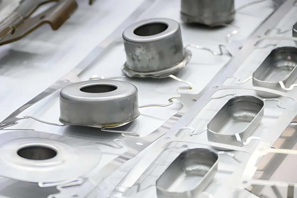
After drawing operations are complete, supplementary operations are often required to fully develop the parts. Examples include cutting away excess material from formed parts, creating holes, and enhancing surface finishes.
These supplemental operations are typically planned during the design phase to ensure correct orientation and minimize rework.
Proper post-processing ensures that all specifications related to dimensions and functionality are met before commencing assembly.
Practical Note
Most problems associated with deep drawing stem from improper management of material flow rather than from any single parameter. Successful deep drawing requires that all variables work synergistically.
Secondary Operations and Modifications in Deep Drawn Parts
Deep drawing creates base shapes, but additional operations are required to meet final design needs; additional operations can also provide structural support or improve assembly characteristics.
Additional features can either be added during forming stages or as secondary operations after the main draw (drawing).
Adding Strength with Beads, Ribs, and Flanges
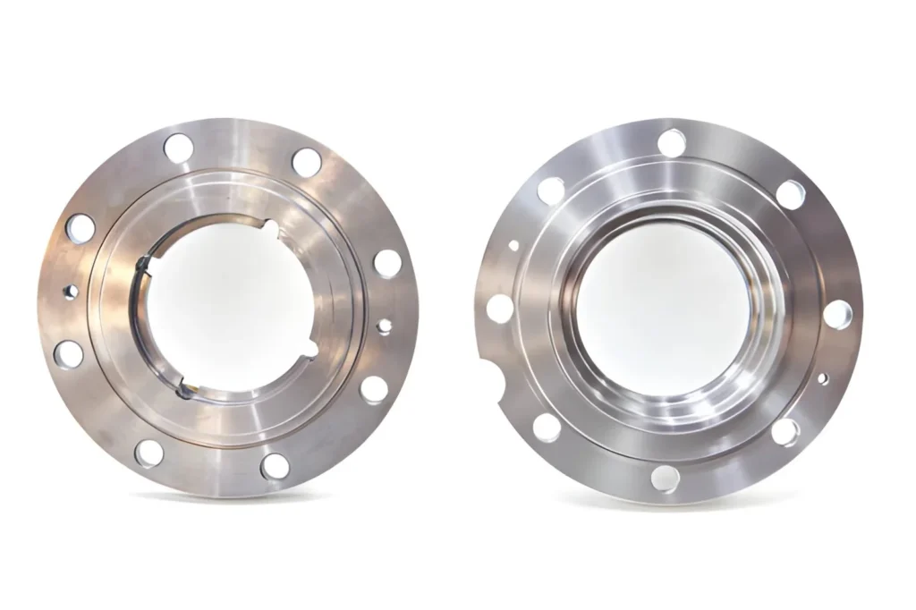
Deep-drawn parts may become too thin in certain areas of their structure. In many cases, adding features such as beads, ribs, and flanges can improve part stiffness without adding material.
These features allow designers to create lighter-weight parts at reduced overall cost while providing the necessary strength to maintain part integrity.
Bulging for Shape Expansion
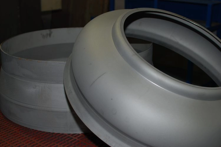
Bulging is a viable option if you want to add volume to a particular area of your part after drawing. This can be achieved using internal pressure or flexible tooling, such as rubber- or fluid-based systems.
Bulging is most often used in cylindrical or shell-type products to increase volume or modify the shape of various sections. You can control the amount of bulge so that all areas of the part bulge uniformly, or you can customize different areas to have varying amounts of bulge.
Coining for Surface Detail and Accuracy
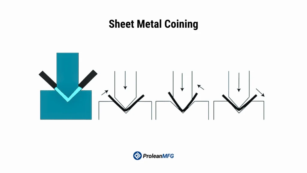
Sheet metal coining process
Coining involves compressing material between closed dies, forcing it to take the exact shape of the dies. Coining is typically performed at very high pressures.
The primary use for coinning is creating fine detail in a product. When precise dimensions are critical and a highly defined surface finish is required, coining can be used. It can also enhance surface finishes in local areas.
Curling for Safe and Functional Edges
Curling is used to curl over sharp corners in open-ended drawings. Once curled over, sharp corners no longer exist, thus making the part safer to handle.
Additionally, curling increases the rigidity of the corner itself and provides a means to prepare the part for assembly. For example, curling prepares the part to fit with another component or enhances the corner’s ability to withstand wear and tear.
Dimpling for Fastener Seating
Dimpling creates a small depression in the material so that a screw or rivet sits flush with the top surface.
Dimpling is most often utilized for parts designed for assembly applications. By providing a flat outer surface, Dimpling facilitates fitment with adjacent components and eliminates potential interferences during installation.
Embossing for Features and Identification
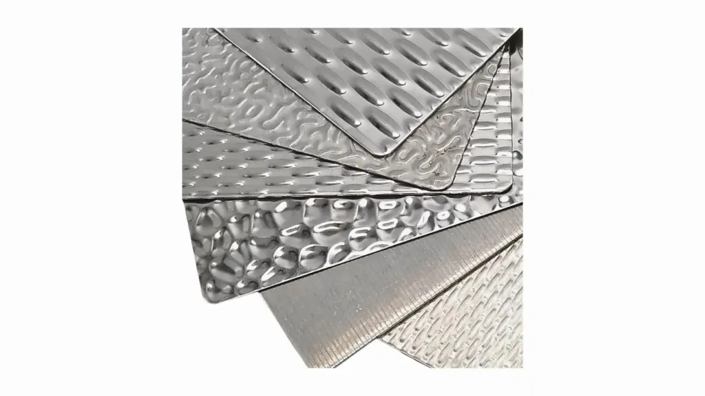
Embossed stainless steel sheet
Embossing creates both raised and depressed designs on the part’s surface without requiring significant changes to the part’s material thickness.
Embossing is generally used to add product ID, logos, etc. Additionally, embossing can be used to create shallow functional elements. Typically, embossing is a rapid process and is often an integral part of stamping.
Hole Flanging and Extruding
A flange is formed on the outside of a hole using hole flanging. As a result of this flange, increased strength is provided to the hole.
A better method for attaching threaded fasteners is established because the hole’s load-bearing capacity has been enhanced.
When threads need to be inserted into a thin sheet metal product, Hole Flanging becomes essential. It enables load distribution across the entire circumference of the hole, rather than having it concentrated near the center of a flat hole.
Piercing and Hole Making
After drawing, Holes can be made in a workpiece using punch/ drill press techniques. Holes are drilled/punched into a workpiece for various reasons, including to facilitate attachment/assembly of parts, for ventilation, etc.
The position/location and precision of Holes in a finished product are critical to ensure accurate alignment during final application.
Ironing for Thickness Control
Ironing produces a smoother surface than can be achieved with conventional manufacturing techniques and simultaneously reduces wall thickness. Material is pressed through a smaller space, which smoothes and polishes surfaces and reduces wall thickness.
Typical examples include food containers or beverage cans. Uniform wall thickness and a smooth finish are required properties for these items.
Marking for Identification
Identification information (such as serial numbers, codes, symbols) can be permanently attached to a part via marking techniques.
Generally speaking, marking techniques involve stamping/engraving Identification information onto a part either during or after forming. This aids in tracking, quality control, and assembly activities related to parts.
Necking for Diameter Reduction
Necking decreases the diameters of cylindrical sections. Multiple passes are sometimes used to avoid cracking the material. Cylindrical parts (e.g., containers/housings) often require multiple diametric reductions; therefore, necking is employed in these applications.
Notching for Clearance and Fit
Notching is the process of cutting out areas along the edges of parts to provide clearance or improve fit.
Notching is primarily used when parts must fit together properly and require clearance during installation.
Threading for Assembly
Fasteners are created with threading to join two parts of a product. Depending on the type and material, fasteners may be tapped into place or formed with specialized tools. This allows assemblies to be completed directly from the original piece (without needing any intermediate attachments).
Trimming for Final Shape
Trimming removes excess material left after drawing and brings the part to its final dimensions. It is one of the last steps in the process and ensures that edges follow the required profile for proper fit and finish.
Comparison of Deep Draw Stamping with Other Metal Forming Methods
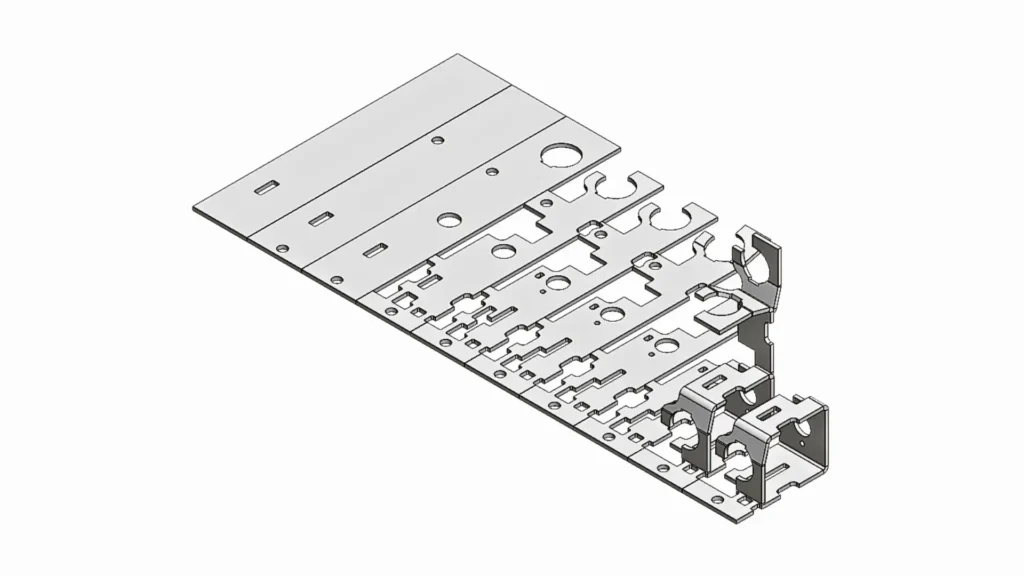
Progressive die stamping
Table 1: Deep Draw Stamping vs Progressive vs Transfer die & Multi-side Stamping
| Parameter | Deep Draw Stamping | Progressive Die Stamping | Transfer Die Stamping | Multi-Slide Stamping |
| Forming Mechanism | Plastic deformation through punch pulling the sheet into the die cavity | Incremental forming through sequential die stations | The part moved mechanically between dedicated dies | Simultaneous forming using multiple sliding tool heads |
| Material Flow Behavior | Continuous radial and axial flow with controlled thinning | Localized deformation at each station | Discrete forming at each die stage | Multi-directional flow synchronized tool motion |
| Stress Condition | High tensile stress in the cup wall, compression at the flange | Mixed bending and shearing stresses | Varies per operation stage | Localized bending and shear at multiple axes |
| Typical Draw Ratio / Forming Limit | Governed by draw ratio (~1.8–2.2 for the first draw for steels) | Not applicable (no deep cavity forming) | Moderate, depends on stage design | Not applicable for deep forming |
| Part Geometry Capability | Deep, hollow, axisymmetric, or box-shaped parts | Flat to moderately complex stamped profiles | Complex multi-stage formed geometries | Small, intricate, multi-feature components |
| Tooling System | Single punch-die with blank holder system | Progressive die with multiple stations | Multiple independent die sets with a transfer mechanism | Multi-slide cam-driven tooling system |
| Thickness Suitability | Thin to medium sheet metals | Thin sheets | Thin to medium sheets | Thin strip material only |
| Dimensional Control | Strong wall thickness uniformity, slight thinning at corners | High repeatability for planar features | High accuracy across sequential operations | Very high precision for small features |
| Key Limiting Factor | Risk of wrinkling or tearing due to poor material flow control | Limited capability for deep cavity forming | High tooling complexity and setup time | Restricted part size and thickness range |
Where Deep Drawn Parts are Used
Deep drawing is used to create closed shapes with uniform walls that do not require joints. Therefore, this process is generally chosen when a part needs to maintain its shape under an external load, or if it will contain liquids, gases, or other internal components.
Battery Housings and Sealed Components
This process is utilized to create battery housings (and cylindrical) housings using one piece of material. Because the process does not add a seam, the created housing will provide an enclosed area for internal components.
Parts made by this method are found in all types of electric vehicles, consumer electronics, and energy storage equipment. As well, because of the uniformity of both wall thickness and overall shape, the internal cell(s) may fit uniformly within the housing.
Additionally, the rigidity of the walls will help support the structure throughout the component’s life cycle.
Medical Components and Small Precision Parts
For medical purposes, deep drawing is used to create precision metal parts with specific geometrical and dimensional characteristics.
Examples of these types of parts include enclosures for electronic devices, surgical instrumentation, and various small enclosures. This process allows for repetitive manufacturing of thin-walled components that can be post-processed or assembled without significant modifications.
Metal Diaphragms for Pressure Systems
Deep drawing is also used to manufacture thin metal diaphragms that flex under internal pressure.
Examples of how these diaphragms are used include valve and regulator systems and various types of sensors. By controlling both the thickness and geometry of the diaphragm through the deep-drawing process, it ensures proper flexing during operation and return to its original position without failure.
Automotive Parts and Housings
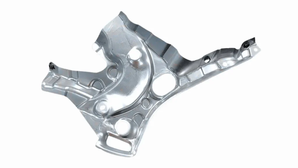
Automotive metal stamping part
In the automotive industry, deep drawing is used to produce such items as fuel tanks, filter housings, and structural shell components.
All of these items are manufactured as single pieces before being assembled into complete systems. Through deep drawing, manufacturers have achieved high-volume production while maintaining consistent geometries for subsequent assembly processes.
Aerospace Enclosures and Lightweight Shells
Due to stringent weight requirements for many aerospace components, deep-drawn parts or components are often required with minimal deviation from their intended design.
As such, an aerospace manufacturer uses deep drawing to fabricate enclosure-type housings and covers from aluminum or similar materials. The process provides a means to consistently produce parts with controlled wall thicknesses while minimizing the number of assembly seams.
Consumer Products and Equipment Parts
Deep drawing stamping is also widely employed to produce products such as containers, appliances, and metal covers.
Through deep drawing, manufacturers can produce large quantities of parts with consistent geometric shapes. After production, these parts may be further finished or assembled in accordance with product specifications.
Key Considerations in Deep Draw Stamping
Deep draw stamping can produce strong, seamless parts. The process’s performance, however, is highly dependent on both the design and the controls used.
There are a few key points to consider when planning deep-draw parts to help prevent defective parts and rework.
MateriUtilization and Blank Design
One of the major advantages of deep draw stamping is the efficient use of sheet material, as all final part geometry is created by forming the single blank with minimal joining. Even though sheet material is used very efficiently in deep drawing, it does not automatically mean that optimized material usage has been achieved.
The size of the blank must be calculated based on the final part geometry, including height, corner radius, and any trimming allowance. If the blank is too large, excess trimming will result in waste. If the blank is too small, the part may fail due to insufficient material flow during forming.
Dimensional Accuracy and Tooling Control
To develop accurate die and punch designs, all final dimensions are defined by the tooling geometry. Even small errors in die clearance or punch alignment can lead to variation in wall thickness or shape distortion.
The material thickness also directly affects the final part size. Thicker sheets resist deformation more than thinner sheets, altering the material’s flow behavior during drawing. To obtain consistent results, the tooling clearance must match the actual sheet thickness, not nominal values.
Draft Angle and Shape Formation Limits
It is usually impossible to create perfect vertical walls due to deep drawing. Sometimes, slight draft angles are naturally formed as the material is pulled into the die cavity.
This effect is more evident when working with deeper parts or high-strength materials. Designers generally account for this in the modeling so that the final formed shape still meets functional requirements.
Wall Thinning and Thickness Variation
The material is not evenly distributed throughout the part. The wall area of the pars generally becomes thinner as they are pulled and elongated. This can result in areas that are weaker than others.
Because some areas of the part deform more than others, control parameters such as the punch radius, lubrication system, and the amount by which you pull the metal (draw ratio) are used to manage how the material moves and minimize differences, i.e., thinning.
Manufacturing Support for Deep Draw Stamping at Prolean MFG
At Prolean MFG, we focus on making deep drawing practical for production, not just for forming. Our custom metal stamping services and support include:
- We assist in selecting sheet thickness in the range of 0.3 mm to 3.0 mm based on draw depth and material flow limits. This helps reduce failure risks, such as tearing or excessive thinning during forming.
- We also work on die clearance and punch-radius matching, typically in the range of 4× to 10× the material thickness, to achieve smoother flow and reduced wrinkling in initial draws.
- For production planning, we help define realistic batch ranges, from prototype runs (10-50 pcs) to scaled production (10,000+ pcs), based on part complexity and tooling setup.
So, contact us today, and get a detailed quote with free DFM review and guidance from our engineers!