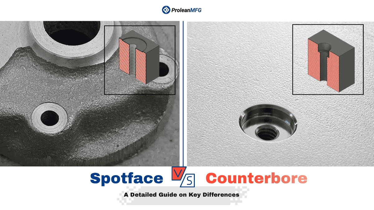

Spotface and counterbore are two types of engineering holes. Spotface is a shallow facing at the end of a hole and provides a smooth, flat fastener seating on irregular surfaces, whereas a counterbore fully recesses the fastener head with tighter tolerances (±0.02–0.05 mm) and offers a smoother finish, but costs more.
Both spotface and counterbore holes are used in assembly, but the spotface is suitable for uneven surfaces, and the counterbore is for recessed seating and flush assembly.
You must consider several factors, from the hole design & tool selection to post-machining treatments. In precision CNC machining & fastening assembly, a small deviation or error in hole specification can result in weak connections, misalignments, and even assembly failure.
This article will guide you through Spotface vs Counterbore hole design, callout symbols, and machining processes.
What is a Spotface Hole?
Spotface holes
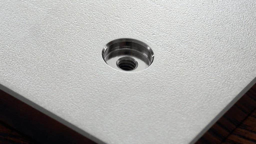
First, what is spotface? A spotface hole is a cylindrical hole with a smooth, flat surface for the fastener head on the workpiece. It means the screw head does not sit below the workpiece surface level; instead, the spotface provides a mating surface.
This hole is used in workpieces with uneven surfaces and can impact the mating strength, alignment, and load distribution. For instance, die-casting parts, sealing components, and structural assemblies.
What is a Counterbore Hole?
Counterbore hole
A counterbore is a deep hole with a recess of a certain depth from the hole’s starting point, allowing the fastener head to sit properly and be hidden below (or flush) the workpiece surface. These holes protect bolts, screws, and other fasteners while enhancing aesthetics.
In complex assemblies, and parts requiring sliding surface counterbore holes are beneficial. Some examples include automobile engines, heavy machinery, and conveyor systems.
Spotface vs Counterbore Symbol: Representation in Engineering Drawing
In Engineering drawing, the callout for spotface and counterbore is different. The “⌴” represents the counterbore symbol, whereas the letter “SF” is combined inside it in a spotface symbol.
Depth (↧) and diameter (⌀) are also added with corresponding spotface and counterbore symbols. However, it might not be included for spotface in some cases.
Let’s look at the visual representation of counterbore and spotface symbols below.
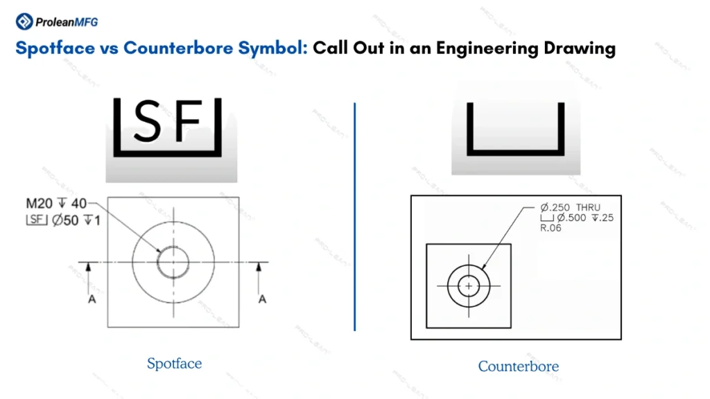
Spotface vs counterbore symbol
Furthermore, these symbols are defined under ASME Y14.5 Standard [1]. You can also find other symbols and specifications in this GD&T standard.
Spotface vs Counterbore: Shape and Size
Both are coaxial cylindrical holes, but the counterbore shape includes a large bore at the hole starting point to fit the screw or bolt head. Counterbore sizes are always specified in engineering drawings, but spotface depth might not always be specified.
If an engineering drawing does not specify spotface size, you must understand it through an indication of the spotface symbol.
The size of the counterbore is head diameter plus desired clearance. On the other hand, the sopotface depth is not precise,~ 0.1-2mm, based on the part dimensions & fastener head size.
Spotface vs Counterbore: Depth
The depth of the main hole(longer hole) depends on the length of the fastener shaft, and the difference between the spotface and counterbore lies in the depth of the coaxial cavities at the top. The hole counterbore is much deeper than the spotface.
The shallow spotface profile only provides a flat surface, whereas counterbore depth accommodates the full head. A typical spotface depth is ~ 0.1 to 1 mm. However, it varies based on surface unevenness and material thickness. For instance, 0.1 or 0.2 mm can be enough for a fine-machined surface, but you need 2 mm (or more) for rough-cast parts [2].
Spotface vs Counterbore: Functions
The primary function of a spotface is to provide a smooth surface for fastener seating, whereas a counterbore houses the fastener head.
- Spotface: Surface waviness removal, seating surface, efficient load distribution, etc.
- Counterbore: Deep recesses, flush surfaces. functional clearance, protection for fastener heads, and aesthetic appeal.
Spotface vs Counterbore: Tolerance and Surface Finish
Counterbores are more accurate, with a typical tolerance range of ±0.02 to ±0.05 mm. On the other hand, general tolerance for spotface is ±0.25 mm. This is because the main goal of Spotface is to achieve flat seating of the fastener head, not precision.
Consequently, spotfaces are relatively rougher, and the roughness value (Ra) lies between ~6.3 and 3.2 µm, whereas it is as low as ~1.6 µm for counterbores. The counterbore needs to be precise and smooth to fit the head perfectly beneath the surface of the part.
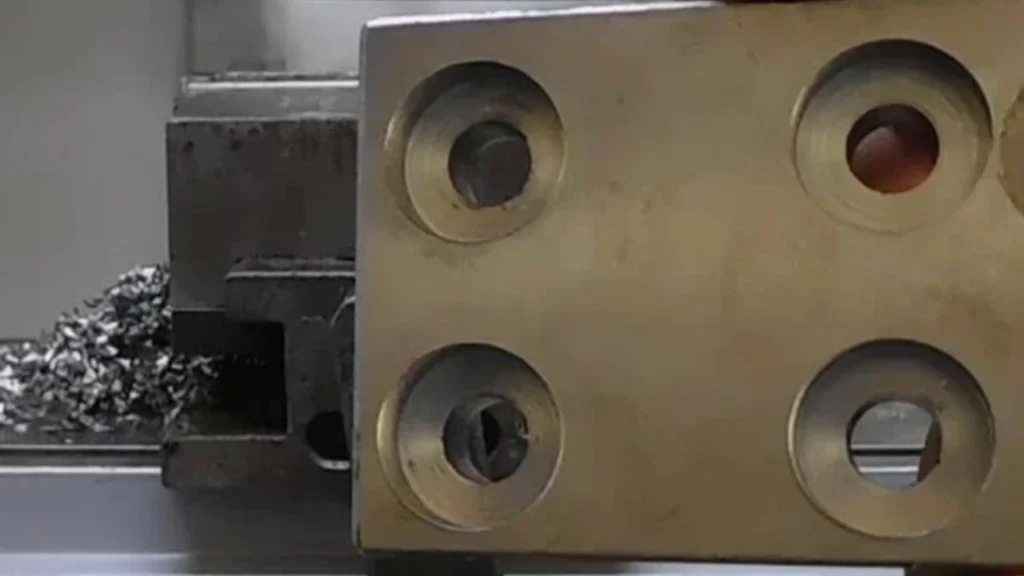
Spotface vs Counterbore: Machining Tools
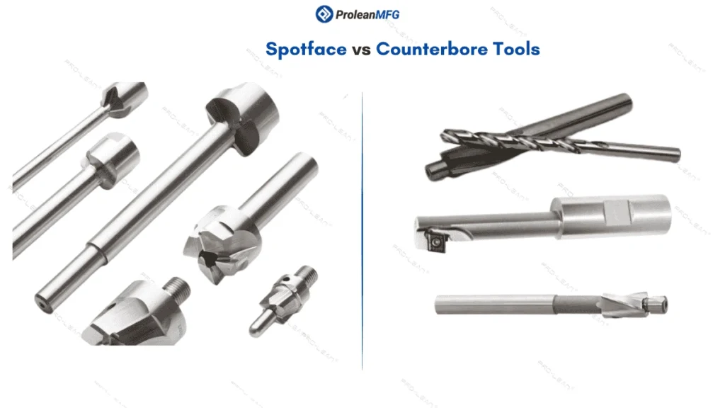
Spotface vs counterbore tools
Spotface machining (or spotfacing) uses tools with flat-bottom cutting faces, but the counterbore machining tools are more diverse. Subsequently, the counterboring tools mostly include a central guide pin to pilot the counterbore.
- Counterbore Tools: Solid, interchangeable, and drill & chamfer counterbores.
- Spotface Tools: Spotface cutters, shallow counterbore cutters, face mill cutters.
- Tooling Cost: Counterboring tools cost more, from $20 to $200/per tool. In contrast, spotfacing tools cost around $20 and $60/per tool.
Based on the material type, you also need to consider the tool material and coating, such as TiN and TiALN.
Spotface vs Counterbore: Industrial Applications
Both hole countebore and spotface are used to secure fasteners in mechanical components & assemblies across industries; the difference lies in how and where they are used. Counterbores are chosen for strong connections, to hide protrusions, and for precise alignment. Spotfaces are used to secure a stable and strong seat on rougher and wavy surfaces
Next, the table below outlines the application examples of spotface vs counterbore in automotive, aerospace, heavy machinery, and electronics industries.
| Industry | Spotface Applications | Counterbore Applications |
| Automotive | Suspension arm, steering parts, and bolt pads of an engine block | Cylinder head, transmission housing, dashboard panel, and drivetrain. |
| Aerospace | Airframe parts, engine mounts, structural members, and turbine couplings. | Landing gear parts, aircraft skin, and interior panels. |
| Heavy Machinery | Fixtures, equipment housings, brackets, and casting frames. | Gearbox casings, high-load joint assembly, and structural frames. |
| Electronics | Connector seating, sensor mounting pads, control panel, and enclosures. | Consumer electronics, PCB components, and heat sink mounts. |
Hole Counterbore and Spotface Machining Processes
The same machining process can perform counterboring and spotfacing; spotfacing involves less material removal than counterboring. Consequently, they use either different or the same tool, distinct machining variables, and setups. CNC and manual milling are two popular machining processes for them.
- Manual Milling: The operator manually controls the material removal, less precise and slower.
- CNC Milling: It uses a CNC program to drill a pilot hole and counterbore sequentially. CNC milling offers higher precision and finish quality.
The Stepwise Process of Counterbore and Spotface Machining
Counterbore machining process
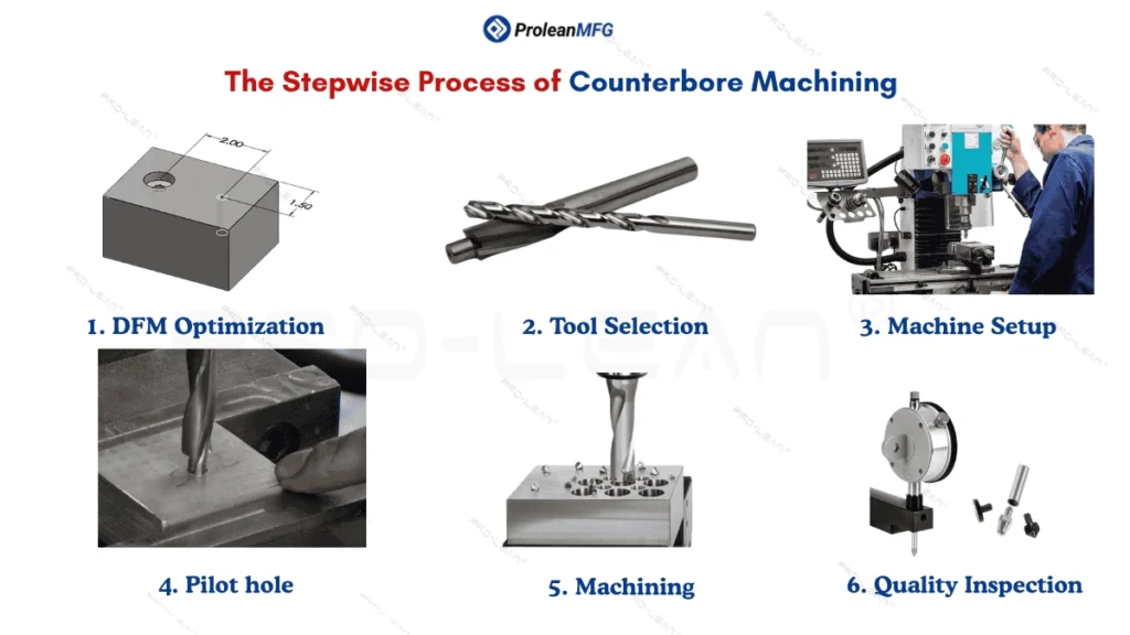
The counterbore and spotface Machining process involves multiple steps, including DFM optimization, tool selection, machine setup, creating a pilot hole, hole machining, and final inspections.
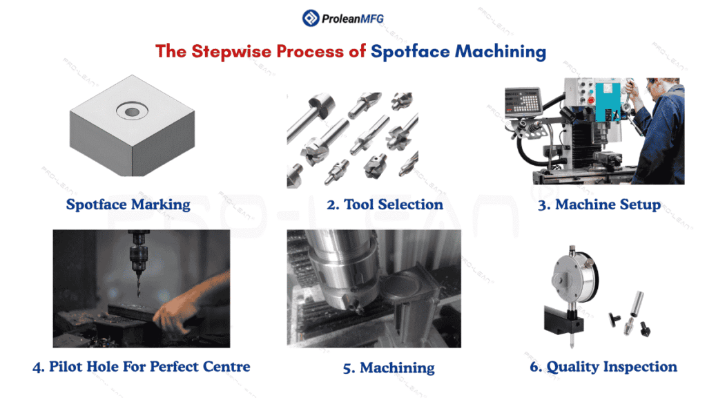
Spotfacing steps
The typical process flow is similar for both types of holes. Sometimes, you can also use a single tool for spotfacing and counterboring.
Let’s break down the step-wise process flow.
- DFM Optimization: Adjust the counterbore or spotface size and tolerance based on the equipment’s capabilities and the machining process.
- Tool Selection: Choose a suitable machining tool based on hole diameter, depth, and material type.
- Machine Setup: Clamp the tool & workpiece, and set machining parameters such as feed rate and spindle speed. If you are using a CNC mill, upload a G-code file as well.
- Pilot Hole: Especially for counterbores, create a pilot hole to guide the further machining process. It helps to ensure the alignment and concentricity of two holes.
- Hole Machining: Following the pilot hole, create the counterbore to the predetermined depth. If you are making spotface, remove material to create a uniform, level surface.
- Inspection & Measurement: Inspect the holes for possible defects and perform dimensional and positional measurements to ensure precision.
Choosing Counterbore Dimensions
Screw(fastener) diameter, counterbore diameter, counterbore depth, and clearance are the key dimensions for a counterbore. You must define and label these dimensions in the engineering drawing.
While choosing counterbore hole dimensions, start with the diameter of the fastener (screw). Then, look for the corresponding dimensions in the data table below.
| Fastener/Screw Diameter | Counterbore Diameter (mm) | Counterbore Depth (mm) | Clearance Dia (Normal) (mm) | Clearance Dia (Close) (mm) |
| M1.6 | 3.5 | 1.6 | 1.95 | 1.8 |
| M2 | 4.4 | 2 | 2.4 | 2.2 |
| M2.5 | 5.4 | 2.5 | 3 | 2.7 |
| M3 | 6.5 | 3 | 3.7 | 3.4 |
| M4 | 8.25 | 4 | 4.8 | 4.4 |
| M5 | 9.75 | 5 | 5.8 | 5.4 |
| M6 | 11.2 | 6 | 6.8 | 6.4 |
| M8 | 14.5 | 8 | 8.8 | 8.4 |
| M10 | 17.5 | 10 | 10.8 | 10.5 |
| M12 | 19.5 | 12 | 13 | 12.5 |
| M14 | 22.5 | 14 | 15 | 14.5 |
| M16 | 25.5 | 16 | 17 | 16.5 |
| M20 | 31.5 | 20 | 21 | 20.5 |
| M24 | 37.5 | 24 | 25 | 24.5 |
| M30 | 47.5 | 30 | 31.5 | 31 |
| M36 | 56.5 | 36 | 37.5 | 37 |
| M42 | 66 | 42 | 44 | 43 |
Source: Fmcacaride [3]
How to specify the Counterbore Dimensions in an Engineering Drawing?
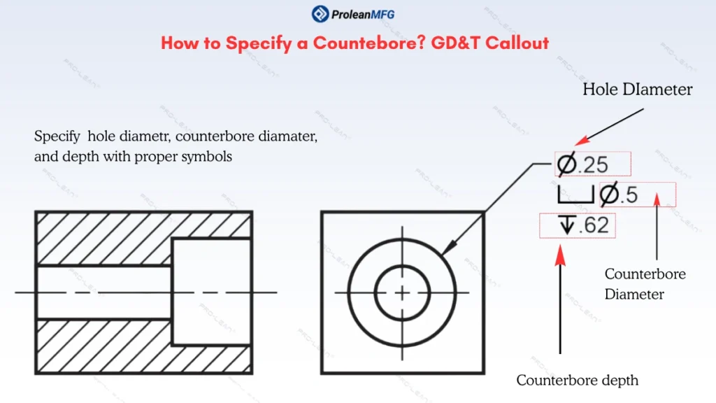
You must call out the counterbore in an engineering drawing with proper GD&T symbols and dimensions. Call out counterbore symbol “⌴” with counerbore diameter and specify the depth (↧).
Let’s look at the example of a counterbore callout and dimensioning.
Countersink callout
How to specify the Spotface Dimensions in an Engineering Drawing?
Spotface dimensions( diameter and depth) must be specified in an engineering drawing with a correct callout of the spotface symbol.
The given infographic shows how a spotface of a 50 mm diameter and 1 mm depth is specified in the drawing.
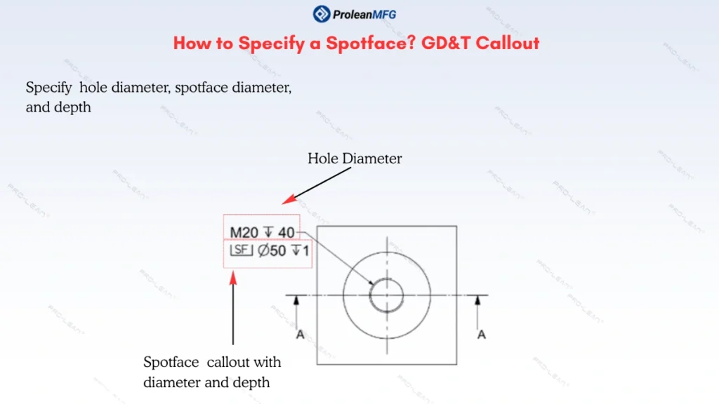
Spotface callout
Counterbore vs Countersink: How are They Different?
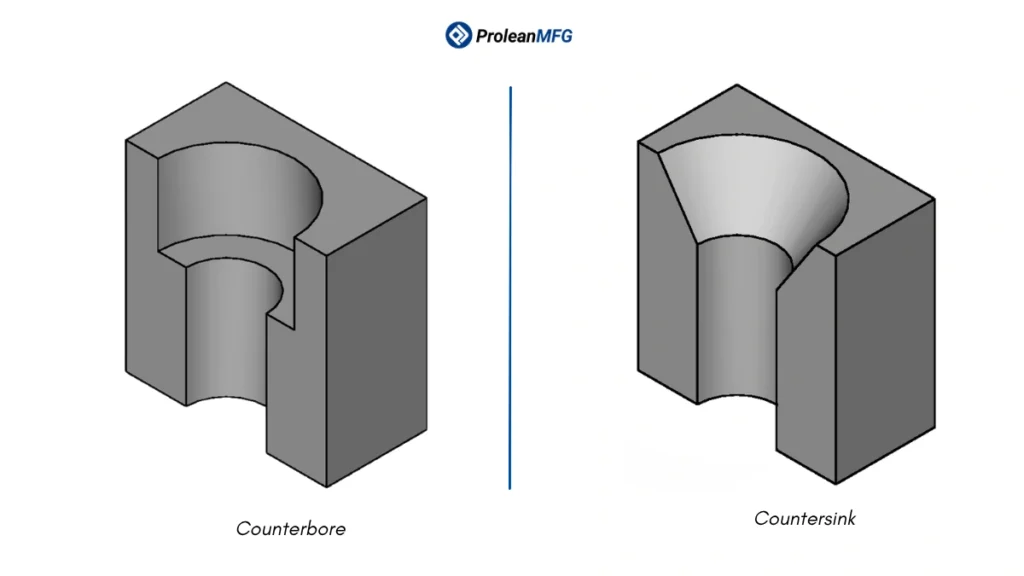
Counterbore vs countersink
Counterbore and countersink both are designed to sit flush with a faster head or surround below the surface level, but counterbore is a cylindrical recess with a flat bottom, and countersink is a conical recess.
The selection between counterbore vs countersink depends on the geometry of the fastener head. For bolt & socket heads, choose counterbore. On the other hand, countersinks are ideal for flat-head screws.
The table below is a comparative summary of counterbore vs countersink.
| Aspect | Counterbore | Countersink |
| Geometry | Large cylindrical cavity with a flat bottom. | Conical and Angled |
| Defining Dimensions | Counterbore diameter and depth. | Countersink angle (typically ~ 82° or 90°) |
| Depth Control | Defined by counterbore dimensions | Based on the countersink angle |
| Best for | Hex heads, sockets, bolts, etc. | Flat-heads |
Spotface Tool Selection: Counterbore Cutters vs End Mills
You can perform spotfacing with counterbore cutters and end mills. If you are choosing counterbore cutters, choose ones with pilots for better accuracy. It also provides excellent control over depth, flatness, and finish.
On the other hand, if you are using end mills, they need CNC circular interpolation for spotfacing.
Tool Selection for Counterboring
Counterbores are the most common tools. Choose aircraft counterbore for thin material & tight tolerances, and cap screws for flush bolt holes.
Interchangeable pilot counterbores can be used for pilot-guided accuracy. Consequently, back counterbore cuts on the reverse side through an existing hole.
Speed and Feed for Spotfacing and Counterboring
Cutting speeds for spotfacing are higher than for counterboring, as it involves less material removal. Consequently, the feed rates are slower to moderate for spotface machining, and controlled & moderate for counterboring.
Furthermore, these machining parameters also differ based on material type.
| Material | Spotfacing | Counterboring | ||
| Cutting speed (SFM) | Feed rate (in/tooth) | Cutting speed (SFM) | Feed rate (in/tooth) | |
| Aluminium 6061 | 700 – 1,000 | 0.003 – 0.006 | 600 – 1,000 | 0.002 – 0.006 |
| Brass | 750 – 1,000 | 0.004 – 0.008 | 700 – 1,000 | 0.003 – 0.007 |
| Copper | 600 – 900 | 0.003 – 0.006 | 500 – 900 | 0.002 – 0.005 |
| Low-carbon steel 1018 | 300 – 420 | 0.002 – 0.005 | 250 – 400 | 0.0015 – 0.004 |
| Stainless steel 304 / 316 | 175 – 260 | 0.0015 – 0.003 | 150 – 250 | 0.001 – 0.003 |
| Stainless steel 400 | 140 – 210 | 0.001 – 0.003 | 125 – 200 | 0.001 – 0.003 |
*Note: these parameters are for general reference, and exact values can differ from one machining project to another.
Common Problems and Troubleshooting
Chatter & vibration, burr formation, workholding & fixturing issues, and tight pilot holes are the key problems in spotface machining & counterboring.
Let’s further break down the causes and prevention strategies.
Chatter and Vibration
This happens because of poor machine rigidity, loose setup, and incorrect cutting parameters. You must ensure the tool length is not oversized and that it has sufficient rigidity to withstand the workpiece’s hardness. If the problem arises, pre-drill a hole before CNC circular interpolation and slightly increase the feed rate.
Burr Formation
Burrr formation mainly occurs due to chattering, poor chip removal, and dull tools. Therefore, perform light chamfering at the tool entry point, use efficient coolant (flood), and replace dull tools.
Workholding & Fixturing Issues
Uneven whorkholding typically occurs with rough-cast or forged surfaces. This is because the clamping jaws could not uniformly hold the material. In such cases, you might need additional support or custom worekholding fixtures.
Tight Pilot Fit
It means the size of the pilot hole is tighter than the tool, which can cause material galling and increase the tool wear. To solve this, check the tool runout and slightly increase the pilot hole diameter.
Reverse Counterbore vs. Reverse Spotface
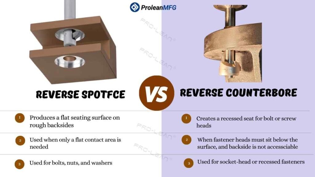
Reverse spotface vs counterbore
What makes reverse counterbore and reverse spotface from their standard forms is that they are machined on the backside(reverse) of the hole without flipping the workpiece. These are beneficial when the backside face is not accessible from the front side. The reverse counterbore provides a large diameter recess, whereas the reverse spotface provides shallow, flat seating at the backside.
Flip-open or back-counterbore tools are used for reverse counterboring, whereas back spotface cutters are used for reverse spotfacing. You can use reverse spotface in cast, forged, or rough machining workpieces when the part has inaccessible back faces. The reverse spotfaces can be used on gearboxes, enclosures, etc.
Other Types of Machining Holes in Manufacturing
Simple hole, blind hole, through hole, tapped hole, tapered hole, and countersink hole are common machining holes, in addition to counterbore and spotface. These types of holes differ in geometry, purpose, functionality, tooling, and other aspects.
Next, the table below shortly defines these types of machining holes.
| Hole Type | Description |
| Simple Hole | It is a simple cylindrical hole of a fixed diameter |
| Blind Hole | A hole that does not pass through the material; instead, it goes to a fixed depth |
| Through Hole | A straight hole that passes through the material |
| Tapped Hole | A hole with internal tapping threads |
| Tapered Hole | A hole that changes diameter gradually from one side to another |
| Countersink Hole | A hole with conical enlargement at staring point |
Which one Should You Use? Spotface or Counterbore
Which one should you use between spotface and counterbore depends on whether the fastener head needs to be hidden or not. You should use spotface on a rougher workpiece surface that does not need a fastener head inside the material surface, and the structural integrity is the top priority; Otherwise, choose counterbore.
Spotface is suitable for suspension arms, engine block, bolt pads, and structural brackets. Meanwhile, the counterbore is ideal for sliding part assemblies, transmission housings, etc.
Summing Up
Deciding between Spotface vs Counterbore in your engineering design of machining parts ultimately depends on whether you want the fastener head below or above the material surface. Furthermore, choosing the right hole finishing feature is not enough; you need to systematically include in drawing, set program & tool accordingly, and consider several potential mistakes and prevention strategies.
If the fastener head must sit below the surface, use a counterbore. For better load distribution and securing the fastener head above the surface, use spotface.
Choosing an experienced manufacturer with advanced machining capabilities is the best decision if you are outsourcing machining parts with spotface, counterbore, or any other types of holes.
At ProleanMFG, our CNC machining service provides comprehensive solutions for your custom manufacturing projects. We have advanced multi-axis( 3, 4, 5, and more) CNC mills to craft your design into reality. Additionally, we also provide DFM consultation, material selection support, prototyping iteration, and surface treatment services.
For further information or a detailed quote, upload your design now!
FAQs
The purpose of spotface is to provide a smooth, flat surface for the stable seating of the fastener head around the hole. It involves minimal material removal to create a uniform finish around a hole on cast, forged, or other types of stock with rough surfaces.
A spotface involves a flat-bottom & shallow cylindrical cut, whereas a countersink includes a conical shape at the hole starting to fit the angled head of a fastener. The choice depends on the geometry of the fastener head. Using a counterbore for cylindrical socket-head fasteners and a countersink for flat-head fasteners provides a precise fit & efficient load distribution.
A spotface typically does not include a defined depth; it should be 0.1–2 mm, which is sufficient to level the surface irregularities. The exact depth depends on surface irregularities, fastener specifications, and surface coating. A common rule for spotface depth in engineering is “ it should be around 1/16 inches”.